

 English
 Español
 italiano
 Deutsch
 0086-13338774804

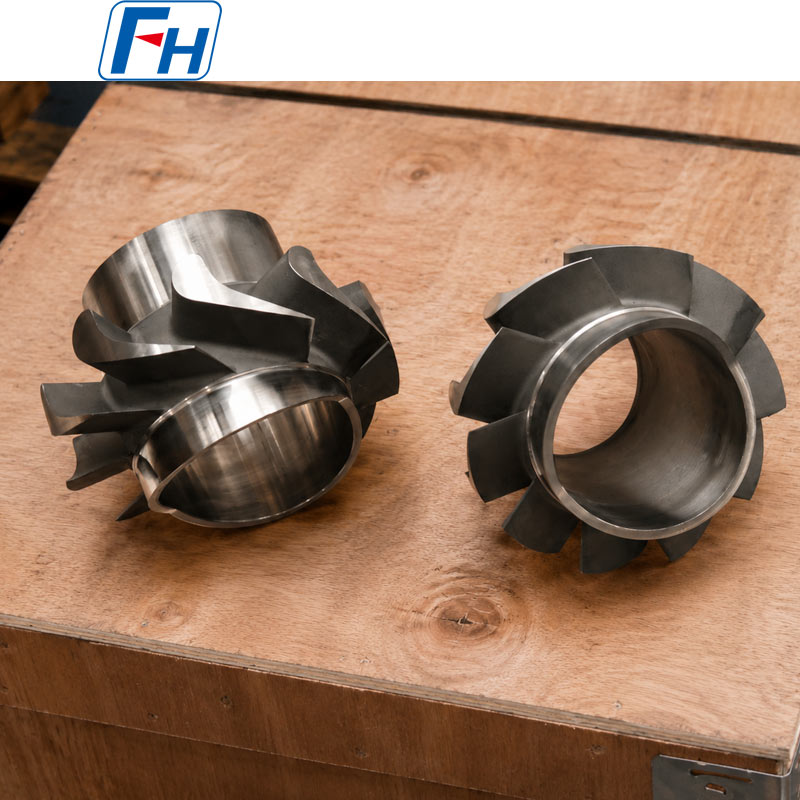
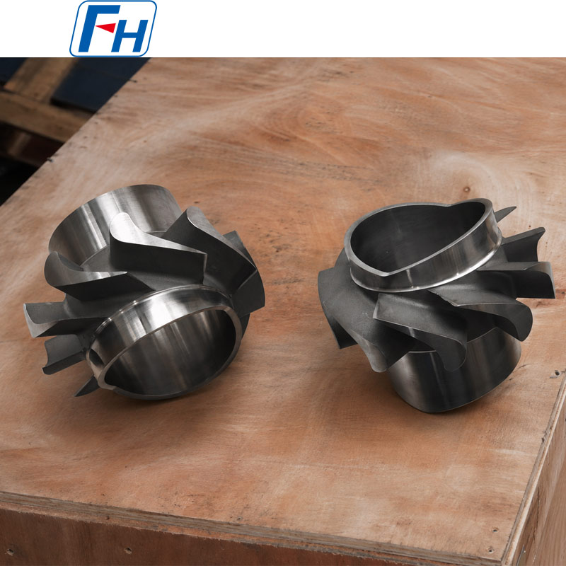
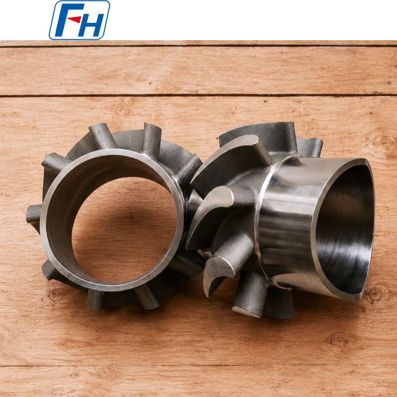

Cobalt Alloy 6 Rotor Impeller for Oil & Gas Equipment
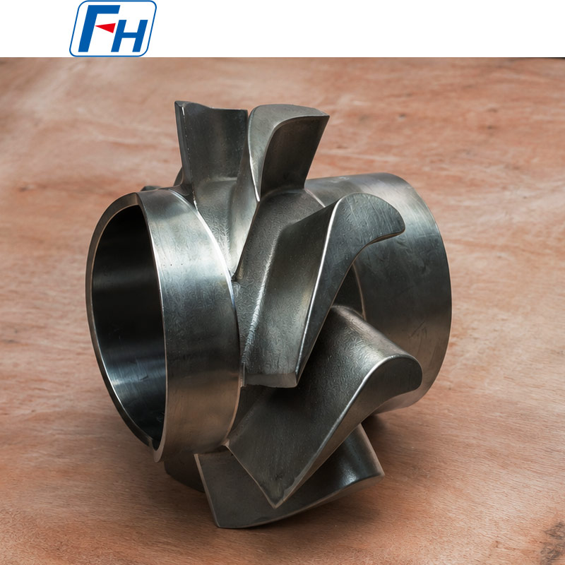
FH® Alloy manufactures custom Cobalt Alloy 6 rotor impellers and rotating components for oil and gas equipment operating under abrasive wear, erosion, corrosion and demanding mechanical conditions.
The components shown feature an integral cylindrical hub with multiple curved vanes. They are produced as customized one-piece castings, followed by precision machining of the bore, hub surfaces and other critical mounting areas.
Each rotor impeller is manufactured according to the customer’s drawing, operating conditions, dimensional tolerances, rotational requirements and inspection specifications.
Product Specifications
| Item | Details |
| Product | Cobalt Alloy 6 Rotor Impeller |
| Alternative Name | Cobalt Alloy Rotor / Rotating Impeller |
| Material | Cobalt Alloy 6 |
| Alloy System | Cobalt-chromium-tungsten alloy |
| Generic Designation | Co-Cr-W Alloy 6 (Stellite 6) |
| Application | Oil and gas equipment |
| Manufacturing Process | Precision investment casting |
| Secondary Processing | Grinding and CNC machining |
| Construction | One-piece cast rotor |
| Surface Condition | As-cast, ground and machined |
| Bore Condition | Rough machined or finish machined |
| Customization | According to customer drawing |
| Manufacturer | FH® Alloy |
Chemical composition, dimensions, hardness, tolerances and acceptance criteria are confirmed according to the customer-approved material specification and drawing.
Material Grade Table
| Stellite 6 Alloy | |||||||||
| Nominal Composition (Mass %) and Physical Properties | |||||||||
| Co | Cr | W | C | Other | Hardness | Density | Melting Range | ||
| Bal. | 27.00-32.00 | 3.00-6.00 | 0.90-1.40 | Ni, Fe, Si, Mn, Mo | 36-45 HRC 380-490 HV |
8.44 g/cm³ 0.305 lb/in³ |
1250-1360ºC 2282-2480ºF |
||
Why Use Cobalt Alloy 6 for Rotor Impellers?
Cobalt Alloy 6 is a cobalt-based alloy containing chromium, tungsten and carbon. This alloy family is used where components require a combination of mechanical wear resistance, elevated-temperature performance and corrosion resistance.
Wear and Erosion Resistance
Rotor impellers used in oil and gas equipment may encounter solids, abrasive particles, high-velocity fluids or repeated surface contact. The cobalt alloy matrix and carbide structure help resist material loss caused by sliding wear, erosion and abrasion.
Resistance to Galling
Cobalt-based alloys are often selected for components exposed to intermittent rubbing or metal-to-metal contact, particularly where conventional stainless steels may experience adhesive wear or galling.
Corrosion Resistance
The chromium-containing alloy structure provides resistance in many industrial and process environments. Final suitability must always be confirmed against the actual fluid composition, temperature, pressure and contaminant level.
Elevated-Temperature Stability
Cobalt Alloy 6 can maintain useful wear-related performance under elevated-temperature conditions where some conventional alloys may soften or deteriorate more rapidly.
One-Piece Complex Geometry
Precision investment casting makes it possible to produce the hub and curved vanes as an integral component. This reduces the need for multiple blade-to-hub welds and allows reinforced vane transitions to be incorporated into the rotor design.
Rotor Impeller Design Features
The customized components shown include:
- Integral cylindrical hub
- Multiple curved rotor vanes
- Reinforced vane-to-hub transitions
- Large internal through-bore
- Machined cylindrical mounting surfaces
- One-piece cast construction
- Complex flow-guiding vane geometry
- Custom inlet and outlet profiles
The following features can be customized:
- Overall rotor diameter
- Hub outside diameter
- Bore diameter and length
- Number of vanes
- Vane angle and curvature
- Vane height and thickness
- Rotation direction
- Mounting structure
- Keyway or internal groove
- Shaft fit and tolerance
- Surface roughness
- Static or dynamic balance requirements
Applications in the Oil and Gas Industry
Custom Cobalt Alloy 6 rotor impellers may be used in:
- Oilfield processing equipment
- Petroleum pumping systems
- High-wear pump assemblies
- Flow-control equipment
- Separation equipment
- Mixing and circulation machinery
- Refinery process equipment
- Petrochemical machinery
- Erosion-resistant rotating assemblies
- Corrosive fluid-handling equipment
- Specialized valve and actuator systems
- Replacement components for discontinued equipment
The exact application of the rotor should be confirmed before production. Operating speed, fluid composition, particle content, pressure, temperature and shaft-loading conditions are especially important for material and process selection.
Precision Investment Casting Process
A typical production route includes:
- Customer drawing and 3D model review
- Casting feasibility and shrinkage analysis
- Tooling and wax-pattern production
- Wax-pattern inspection
- Gating-system design and assembly
- Refractory shell preparation
- Dewaxing and shell preheating
- Cobalt alloy melting and pouring
- Controlled cooling and solidification
- Shell removal and casting cleaning
- Gating and riser removal
- Surface grinding and finishing
- Rough machining of the hub and bore
- Nondestructive testing
- Finish machining of critical dimensions
- Dimensional and runout inspection
- Balancing when specified
- Final documentation and export packaging
Precision Machining Requirements
Because this product is a rotating component, the machining specification should address more than the basic outside dimensions.
Important requirements may include:
- Bore diameter tolerance
- Hub concentricity
- Cylindrical runout
- Face runout
- Bore-to-vane concentricity
- Mounting-face perpendicularity
- Shaft fit
- Keyway dimensions
- Surface roughness
- Machining allowance
- Rotor weight
- Center-of-gravity control
- Balance grade
FH® Alloy can supply the rotor in rough-machined, semi-finished or fully machined condition according to the approved drawing.
Static and Dynamic Balancing
For rotating oil and gas equipment, imbalance may cause vibration, bearing load, noise and premature equipment wear.
Depending on the rotor dimensions and operating speed, the customer may specify:
- Static balancing
- Dynamic balancing
- Permissible residual imbalance
- Balance correction method
- Balance grade
- Test rotational speed
- Balance report requirements
The required balancing criteria should be included in the drawing or purchase specification. FH® Alloy does not apply a balance grade automatically unless it is confirmed by the customer.
Inspection and Quality Control
Available inspection items may include:
- Chemical composition analysis
- Positive Material Identification
- Visual inspection
- Dimensional inspection
- Bore and hub measurement
- Concentricity inspection
- Face and cylindrical runout inspection
- Dye penetrant testing
- Radiographic testing when required
- Hardness testing
- Surface-roughness measurement
- Static or dynamic balancing
- Third-party inspection
Inspection scope and acceptance standards should be agreed before order confirmation.
Available Quality Documentation
Depending on the purchase specification, FH® Alloy can provide:
- Material Test Certificate
- Chemical composition report
- Dimensional inspection report
- Hardness report
- Dye penetrant testing report
- Radiographic testing report
- Machining inspection report
- Balance report
- Certificate of Conformity
- Heat or batch traceability records
- Third-party inspection documents
Why Choose FH® Alloy?
Custom Cobalt Alloy Manufacturing
FH® Alloy produces cobalt alloy rotor impellers according to customer drawings instead of limiting customers to standard catalog sizes.
Complex Investment Castings
Curved vanes, cylindrical hubs and reinforced transitions can be integrated into a single precision casting.
Casting and Machining Coordination
Casting allowance, datum selection and finish-machining requirements can be reviewed together to reduce dimensional inconsistencies between the cast structure and machined mounting surfaces.
Oil and Gas Project Support
FH® Alloy supports customized parts for oilfield, petroleum processing and industrial fluid-handling equipment.
Small and Batch Orders
Both prototype quantities and repeat production batches can be evaluated according to tooling requirements, component dimensions and technical complexity.
Information Required for Quotation
Please provide:
- 2D drawing or 3D model
- Required generic material specification
- Chemical composition requirements
- Overall rotor dimensions
- Bore and hub dimensions
- Vane quantity and geometry
- Direction of rotation
- Dimensional tolerances
- Surface roughness
- Operating speed
- Operating temperature
- Operating pressure
- Fluid or process medium
- Solid-particle content
- Static or dynamic balance requirements
- Nondestructive-testing requirements
- Required quantity
Send your rotor impeller drawing to FH® Alloy for casting review, machining evaluation and quotation.
FAQ
Q1: What material is used for this oil and gas rotor impeller?
The material is identified on the FH® Alloy website as Cobalt Alloy 6, or Co-Cr-W Alloy 6. It is a cobalt-chromium-tungsten alloy selected for components requiring wear resistance, erosion resistance and corrosion resistance.
Q2: Is Cobalt Alloy 6 the same as Stellite 6?
“Stellite” is a registered trademark associated with Kennametal’s proprietary alloy products. Cobalt Alloy 6 is the preferred generic description for FH® Alloy’s website.
The material supplied by FH® Alloy should be defined by an agreed chemical composition, casting specification, hardness requirement and inspection criteria—not represented as genuine branded Stellite® material unless genuine trademarked material is specifically sourced and documented.
Q3: Can FH® Alloy manufacture the rotor according to our existing sample?
Yes. Manufacturing from a sample may be possible, but a drawing or 3D scan is recommended for confirming the bore, vane profile, machining tolerances, direction of rotation and balance requirements.
Q4: Is the rotor cast in one piece?
Yes. The hub and vanes can be produced as an integral investment casting. One-piece construction avoids multiple welded vane joints and is suitable for complex curved profiles.
Q5: Can the internal bore be fully machined?
Yes. The bore, cylindrical hub surfaces and mounting faces can be finish machined according to the customer’s dimensional tolerances and surface-roughness requirements.
Q6: Can you control concentricity and runout?
Yes. Concentricity, face runout and cylindrical runout can be inspected according to the drawing. The required datum system and permissible values must be clearly specified.
Q7: Is dynamic balancing available?
Dynamic balancing can be arranged when the customer provides the operating speed, balance grade, rotor mass, mounting method and permissible residual imbalance.
Q8: What testing is recommended for this product?
Typical inspection may include chemical analysis, dimensional inspection, dye penetrant testing, hardness testing and runout inspection. Radiographic testing and dynamic balancing can be added for critical applications.
Q9: Can you manufacture replacement rotors for oilfield equipment?
Yes. FH® Alloy can evaluate replacement rotors based on drawings, 3D models or samples. The customer should confirm the equipment interface, service conditions and intellectual-property authorization for the replacement design.
Q10: What is the minimum order quantity?
The minimum practical quantity depends on the rotor size, tooling cost, casting complexity and inspection requirements. Prototype and small-batch projects can be evaluated individually.



 Tel: 0510-83310100
  E-mail: info@alloy-casting.com
  Add: Room 1105,Building 6, Jiaye Wealth Center,Wuxi, Jiangsu, P.R.China P.C.:214000.