
 Sep 15, 2026
 Custom 2.4879 Vacuum Furnace Heat Treatment Trays for a Slovenian Customer
Customer Case Study | Structural Redesign, Manufacturing & Delivery
Customer Location: Slovenia
Product: Custom Vacuum Furnace Heat Treatment Trays
Material: 2.4879 Heat-Resistant Alloy
Maximum Temperature: 1060°C
Cooling Method: 3 Bar Nitrogen Gas Cooling
Required Load Capacity: 250 kg per tray
Quantity: 1 Bottom Tray + 2 Intermediate Trays
Project Scope: Engineering Redesign → 3D Modeling → Manufacturing → Final Inspection → Delivery
Manufacturer: Wuxi Junteng Fanghu Alloy Technology Co., Ltd. (FH® Alloy)
Project Overview
FH® Alloy received an inquiry from a Slovenian customer for customized vacuum furnace heat treatment trays manufactured from 2.4879 heat-resistant alloy.
The customer had previously reviewed one of our proposed tray concepts but considered the original solution too heavy for their application. For the new project, they asked FH® Alloy to redesign the trays while also meeting a demanding load requirement of 250 kg per tray.
At the same time, the customer requested the new trays to use increased section thickness compared with the initial dimensional concept.
This created an important engineering challenge:
How to improve load-bearing capability and structural stability without relying only on excessive material and unnecessary weight.
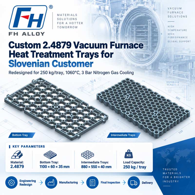
Based on the customer's furnace conditions, loading requirements and dimensional targets, FH® Alloy developed two new tray designs:
The final 3D models were then used as the basis for manufacturing, final inspection and shipment.
Customer Requirements
The customer provided the following operating and design requirements:
| Item | Requirement |
| Customer | Slovenia |
| Furnace Type | Vacuum Heat Treatment Furnace |
| Material | 2.4879 |
| Maximum Temperature | 1060°C |
| Cooling Method | 3 Bar Nitrogen Gas Cooling |
| Load Capacity | 250 kg per tray |
| Bottom Tray Quantity | 1 pc |
| Intermediate Tray Quantity | 2 pcs |
| Project Type | Custom Redesign |
| FH® Alloy Scope | Design, Manufacturing, Inspection & Delivery |
The original requested dimensions were:
Bottom Tray:
1100 × 60 × 25 mm
Intermediate Trays:
550 × 880 × 25 mm
After further engineering review and customer discussion, the final designs were revised.
Final Designed Dimensions
Bottom Tray
Final Size:
1100 × 60 × 35 mm
Quantity:
1 pc
This design is shown in the first 3D model.
Intermediate Trays
Final Size:
880 × 550 × 40 mm
Quantity:
2 pcs
This design is shown in the second 3D model.
The increased section dimensions were incorporated into the final designs based on the customer's updated requirement for structural strength and 250 kg load capacity per tray.
Engineering Challenge: Weight vs. Load Capacity
One of the most important aspects of this project was the relationship between tray weight and structural performance.
The customer had previously considered an earlier recommended tray solution too heavy.
However, for the new design they also required:
Simply adding more material would not be an ideal engineering solution.
FH® Alloy therefore focused on improving the structural efficiency of the tray rather than increasing mass without control.
The design needed to balance:
Tray Weight + Section Thickness + High-Temperature Strength + 250 kg Load Capacity
Vacuum Furnace Operating Conditions
The trays are intended for vacuum heat treatment at temperatures up to:
1060°C
followed by:
3 Bar nitrogen gas cooling
This operating environment places demanding requirements on furnace tooling.
The trays must maintain structural stability during:
These factors were considered during the redesign stage.
Why 2.4879 Was Used
The customer specified 2.4879 for the project.
2.4879 is used in demanding high-temperature industrial applications where good thermal and mechanical performance is required.
For furnace tooling, material selection must be considered together with structural design because even a suitable high-temperature alloy can deform if:
For this project, FH® Alloy therefore treated material and structure as one engineering system.
Bottom Tray Design
The first final design is the bottom tray.
The tray uses an open load-bearing structure with multiple interconnected support sections.
The design incorporates:
The objective was to distribute the 250 kg load across the tray and reduce excessive stress concentration during high-temperature service.
Intermediate Tray Design
The second design is the intermediate tray, with a final size of:
880 × 550 × 40 mm
The tray uses a dense open-cell structure.
This design helps combine:
The geometry was developed specifically for the customer's required furnace loading arrangement.
Open-Structure Design for Nitrogen Cooling
Because the trays are used with 3 Bar nitrogen gas cooling, an open structural layout is important.
The open-cell design allows cooling gas to pass through the tray more effectively than a closed or overly solid structure.
This can support:
The open structure also helps reduce material usage compared with a completely solid tray.
Designed for 250 kg Per Tray
The customer specifically required:
250 kg load capacity for each tray
This requirement was central to the redesign.
FH® Alloy evaluated the load-bearing structure based on:
Rather than treating the 250 kg figure as a room-temperature static load only, the structure was developed with the actual furnace application in mind.
From Customer Feedback to Final Design
This project demonstrates how customer feedback can be converted into a new engineering solution.
The process began with a previous concept that the customer considered too heavy.
The new development process then followed:
Previous Design Feedback
↓
New Loading Requirement
↓
Updated Thickness Requirement
↓
Vacuum Furnace Condition Review
↓
Structural Redesign
↓
Final 3D Models
↓
Manufacturing
↓
Final Inspection
↓
Delivery
This approach allowed FH® Alloy to develop a new solution rather than simply reproducing the earlier concept.
Manufacturing
After the final designs were confirmed, FH® Alloy proceeded with production of:
All components were manufactured according to the approved engineering models and customer requirements.
Production focused on controlling:
Final Quality Inspection
Before shipment, FH® Alloy carried out final inspection of the completed trays.
The inspection included:
Dimensional Inspection
Verification of the main dimensions and section heights against the approved drawings.
Structural Inspection
Checking the load-bearing structure, support areas and overall tray geometry.
Appearance Inspection
Review of overall manufacturing condition and surface quality.
Drawing Conformity
Confirmation that the finished trays matched the approved 3D engineering designs.
After the inspection was completed, the trays were prepared for shipment to the Slovenian customer.
Project Specifications
| Item | Specification |
| Product | Vacuum Furnace Heat Treatment Trays |
| Customer Location | Slovenia |
| Material | 2.4879 |
| Maximum Temperature | 1060°C |
| Cooling Method | 3 Bar Nitrogen Gas Cooling |
| Required Capacity | 250 kg per tray |
| Bottom Tray | 1100 × 60 × 35 mm |
| Bottom Tray Quantity | 1 pc |
| Bottom Tray Quantity | 880 × 550 × 40 mm |
| Intermediate Tray Quantity | 2 pcs |
| Design Type | Customer-Specific Structural Redesign |
| Project Scope | Design → Manufacturing → Inspection → Delivery |
Project Highlights
Customer Feedback-Driven Redesign
The new trays were developed after the customer considered the previous concept too heavy.
250 kg Load Requirement
Each tray was redesigned to meet a required load capacity of 250 kg.
Increased Structural Thickness
The final designs incorporated increased section thickness according to the customer's updated requirements.
Vacuum Furnace Application
The trays were designed for 1060°C operation and 3 Bar nitrogen gas cooling.
Complete Project Execution
FH® Alloy handled the entire process:
Engineering Redesign → 3D Modeling → Manufacturing → Inspection → Shipment
More Than a Standard Furnace Tray
This project demonstrates why customized furnace tooling should not be selected only according to material grade or external dimensions.
A successful tray design must consider:
FH® Alloy combines these parameters when developing customized heat treatment tooling.
Custom Vacuum Furnace Trays by FH® Alloy
Wuxi Junteng Fanghu Alloy Technology Co., Ltd. (FH® Alloy) designs and manufactures customized high-temperature furnace tooling, including:
We support customers from:
Operating Condition Review → Structural Design → 3D Modeling → Manufacturing → Inspection → Delivery
Need to Optimize the Weight or Load Capacity of Your Furnace Tray?
If your existing furnace tray is:
FH® Alloy can evaluate the existing design and develop an optimized replacement.
For engineering evaluation, please provide:
FH® Alloy can develop a customized solution based on your actual furnace conditions and loading requirements.
 CategoryRecent Post


Focus on Designing and Manufacturing Alloy Steel Parts since 2006
 Tel: 0510-83310100
  E-mail: [email protected]
  Office Add: Room 1105,Building 6, Jiaye Wealth Center,Wuxi, Jiangsu, P.R.China P.C.:214000.
  Privacy

 English
 Español
 italiano
 Deutsch
 0086-13338774804
