
 Sep 02, 2026
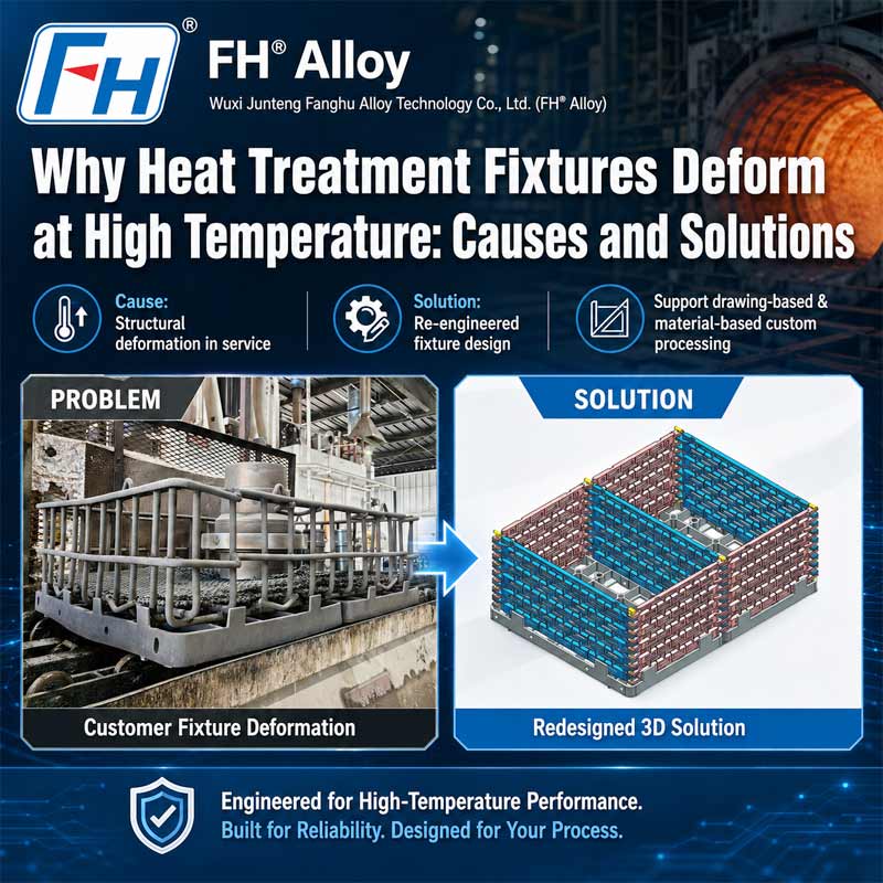
 Deformation is one of the most common problems encountered with heat treatment fixtures used in industrial furnaces.
After repeated furnace cycles, baskets, trays, racks, and support structures may gradually develop:
In severe cases, deforma
tion can affect not only the fixture itself but also the heat treatment process.
Possible consequences include:
High-temperature deformation is rarely caused by one factor alone.
In most applications, it results from a combination of temperature, load, material, structural design, thermal cycling, and operating practice.
Understanding these factors is the first step toward improving fixture reliability.
FH® Alloy manufactures customized heat treatment baskets, trays, racks, and high-temperature furnace fixtures according to customer drawings and actual service conditions.
What Is Heat Treatment Fixture Deformation?
Fixture deformation refers to a permanent change in the original geometry of a heat treatment fixture during service.
For example, a tray that was originally flat may gradually sag in the center.
A basket may develop:
A rack may experience:
The important point is that these changes are often permanent.
Once the fixture cools, it may not return to its original dimensions.
This is different from normal thermal expansion, which occurs temporarily while the material is heated.
1. High-Temperature Creep Is a Major Cause of Deformation
One of the most important mechanisms behind furnace fixture deformation is creep.
Creep is the slow, permanent deformation of a material when it is subjected to stress for a prolonged period at elevated temperature.
For heat treatment fixtures, the stress may come from:
Even if the fixture does not exceed its room-temperature strength, prolonged exposure at high temperature can gradually change its shape.
Typical creep-related problems include:
This is why room-temperature mechanical strength alone cannot be used to judge whether a material is suitable for furnace fixtures.
2. Excessive Loading Accelerates Fixture Deformation
Every fixture should be designed around a defined load.
If the actual production load exceeds the design condition, deformation can occur much faster.
Common overloading situations include:
For example, a basket designed for a distributed load can behave very differently if most of the workpieces are placed in the center.
At elevated temperature, this localized load can significantly increase sagging.
Recommended practice
Production teams should clearly define:
The fixture should then be used within these limits.
3. Poor Load Distribution Creates Local Stress
Two fixtures carrying the same total weight may have very different service lives.
The difference is often where the weight is applied.
If the load is concentrated over a small area, certain structural members may carry much more stress than others.
Typical high-stress locations include:
These areas may deform first.
A more effective design distributes the load through:
Good fixture design should match the reinforcement pattern to the actual workpiece loading pattern.
4. Incorrect Material Selection Can Shorten Fixture Life
Material grade has a major influence on high-temperature deformation.
An alloy may provide excellent strength at room temperature but lose significant load-bearing capability when exposed to furnace temperatures.
Fixture material selection should consider:
Common heat-resistant materials used for furnace fixtures may include:
However, there is no single material that is best for every application.
The correct choice depends on actual operating conditions.
5. Using a Higher Alloy Grade Does Not Automatically Solve Deformation
When an existing fixture deforms too quickly, one common reaction is:
“Use a more expensive alloy.”
Sometimes this works.
Sometimes it does not.
If the real problem is:
changing material alone may not solve the problem.
A better approach is to evaluate:
Material + Design + Load + Furnace Conditions
together.
This is particularly important when replacing an existing fixture.
Simply copying the old drawing in a higher-grade alloy may reproduce the same structural weakness.
6. Long Unsupported Spans Can Cause Sagging
Large baskets and trays often contain long structural members.
At high temperature, long unsupported sections are more likely to sag under load.
The problem becomes more serious when:
Possible design improvements include:
The objective is not necessarily to add material everywhere.
The goal is to reinforce the areas where structural demand is highest.
7. Insufficient Bottom Reinforcement Can Deform Baskets
The bottom of a heat treatment basket often carries the majority of the workpiece load.
If the basket uses an open grid structure, the designer must balance:
Too much open area can reduce support capability.
Too little open area can make the basket unnecessarily heavy and may affect heat transfer.
Common deformation patterns include:
A properly engineered bottom structure is therefore critical for heavy-duty heat treatment baskets.
8. Heat Treatment Trays Can Lose Flatness
Tray flatness is especially important where workpieces require controlled positioning.
Repeated thermal cycles can cause trays to:
Once flatness is lost, components may no longer sit in the intended position.
This can affect:
Tray reinforcement should therefore be designed around:
9. Stackable Fixture Design Can Create Additional Deformation
Stackable baskets and trays improve furnace utilization, but they also transfer load from one layer to another.
If stacking points are poorly designed, the load may become concentrated in limited areas.
Possible problems include:
A good stackable design should provide:
When several loaded fixtures are stacked together, the bottom layer must support substantially more total weight.
This must be considered during design.
10. Repeated Thermal Cycling Can Change Fixture Geometry
Fixtures repeatedly expand during heating and contract during cooling.
Over hundreds of cycles, this repeated movement can lead to:
Thermal cycling becomes more severe when there are:
Large fixtures are particularly sensitive because dimensional changes can become significant over long structural lengths.
11. Insufficient Thermal Expansion Allowance Can Cause Warping
If a fixture structure is too rigid, its components may not be able to expand freely during heating.
This can generate internal stresses.
Examples include:
Possible results include:
Fixture design should therefore distinguish between areas that require rigid positioning and areas that can allow controlled movement.
12. Welded Structures Can Deform Around Joint Areas
For fabricated furnace fixtures, welded joints can become critical locations.
Possible reasons include:
Common failure patterns include:
Improving welding performance may involve:
However, welding quality cannot compensate for a fundamentally weak structural design.
13. Incorrect Handling Can Also Cause Fixture Distortion
Not all fixture deformation occurs inside the furnace.
Heavy fixtures may also be damaged during:
For example, lifting a long loaded fixture from only two poorly located points may cause bending.
Handling requirements should therefore be considered during the design stage.
Possible features include:
14. Furnace Type Influences Deformation Risk
Different furnace systems create different loading and thermal conditions.
Vacuum Furnace Fixtures
Important considerations include:
Pit Furnace Fixtures
Common concerns include:
Roller Hearth Furnace Fixtures
Additional factors include:
Carburizing Furnace Fixtures
Fixture life can be affected by both:
Therefore, material and structural requirements should be evaluated specifically for the carburizing process.
Typical Signs That a Fixture Is Beginning to Fail
Fixture problems should ideally be identified before complete failure occurs.
Operators should watch for:
Regular inspection can help identify progressive deformation.
How to Reduce Heat Treatment Fixture Deformation
There is no universal solution, but several measures can significantly improve performance.
1. Match the Material to the Actual Service Conditions
Evaluate:
2. Optimize Load Distribution
Avoid excessive concentrated loads and ensure structural members carry weight efficiently.
3. Reduce Long Unsupported Spans
Use appropriate:
4. Allow Thermal Expansion
Avoid unnecessary structural constraints.
5. Control Maximum Loading
Do not operate the fixture continuously above its design load.
6. Optimize Fixture Weight
Avoid both:
7. Improve Handling Methods
Use lifting points and handling systems designed for the loaded fixture.
How Can Heat Treatment Fixture Service Life Be Extended?
Extending service life usually requires a combination of:
Correct material + optimized design + proper loading + controlled operation
A practical improvement process may include:
This is usually more effective than simply duplicating an existing fixture.
Information to Provide When a Fixture Is Deforming
If an existing heat treatment fixture has a short service life, providing detailed operating information can help identify the cause.
Recommended information includes:
| Information | Example |
| Fixture dimensions | Length × Width × Height |
| Material | Existing alloy grade |
| Operating temperature | Normal / maximum temperature |
| Furnace type | Vacuum, pit, roller hearth, etc. |
| Atmosphere | Air, vacuum, carburizing, protective gas |
| Workpiece | Shape and dimensions |
| Total load | kg per fixture |
| Cycle | Heating and cooling conditions |
| Service life | Cycles or months |
| Failure area | Photos and deformation location |
Photos of the actual deformed fixture are especially useful.
They can help identify whether the main issue is:
FH® Alloy Custom Heat Treatment Fixture Solutions
FH® Alloy manufactures customized heat treatment fixtures for high-temperature furnace applications.
Products include:
Fixtures can be manufactured according to:
For replacement projects, FH® Alloy can also evaluate existing deformation or failure information before manufacturing a new fixture.
FAQ
Q1: Why does my heat treatment basket sag in the middle?
Common causes include concentrated loading, long unsupported spans, insufficient high-temperature strength, or creep deformation.
Q2: Can changing to a better alloy prevent fixture deformation?
It may help, but material is only one factor. Structural design, load distribution, operating temperature, and thermal expansion should also be evaluated.
Q3: Why does a fixture deform after many cycles instead of immediately?
Progressive deformation is often related to high-temperature creep and repeated thermal cycling.
Q4: Does increasing fixture thickness always prevent warping?
No. Additional thickness can increase stiffness, but poor load paths, long spans, or restricted thermal expansion may still cause deformation.
Q5: Can a deformed fixture design be improved?
Yes. Existing drawings, actual loading information, furnace conditions, service life, and failure photos can be used to evaluate potential improvements.
Q6: What information should I provide for a replacement heat treatment fixture?
Provide dimensions, drawing, material, temperature, furnace atmosphere, workpiece information, total load, cycle conditions, and photos of the failed fixture if available.
Conclusion
High-temperature deformation is one of the most important factors limiting the service life of heat treatment fixtures.
Common causes include:
The most effective solution is usually not a single material upgrade.
Reliable fixture performance requires the correct combination of:
material selection + structural design + loading control + furnace operating conditions
FH® Alloy provides customized heat treatment fixtures for industrial furnaces based on customer drawings and actual service requirements.
For an existing fixture experiencing sagging, bending, cracking, or short service life, provide the drawing, material, furnace type, operating temperature, loading weight, service history, and failure photos for technical evaluation.
 CategoryRecent Post

Focus on Designing and Manufacturing Alloy Steel Parts since 2006
 Tel: 0510-83310100
  E-mail: info@alloy-casting.com
  Office Add: Room 1105,Building 6, Jiaye Wealth Center,Wuxi, Jiangsu, P.R.China P.C.:214000.
  Privacy

 English
 Español
 italiano
 Deutsch
 0086-13338774804
