
 English
 Español
 italiano
 Deutsch
 0086-13338774804


 Heat Resistant Steel Well-type Furnace Fixtures – Max 1150°C, Anti-Carburization")


FH® Push Head + Chain Assembly | Heavy-Duty Furnace Drive & Conveying System
Key Benefits
- Integrated Push Head + Chain System
Designed as a complete assembly – perfect match between push head, chain attachments, and drive sprocket. - High Push Force Capacity
Reinforced push head design withstands high thrust loads – moves heavy tray stacks through furnace without bending or breaking. - Heat & Wear Resistant
High-temperature alloys and specialized heat treatment – resists thermal distortion, abrasion, and oxidation in furnace environments. - Precision Chain Drive
Precision-machined pins, bushings, and side plates – smooth engagement, reduced elongation, and long service life. - Custom Configurations
Any push head size, chain pitch, length, and attachment spacing – designed for your specific furnace layout and tray dimensions.
Technical Specifications
| Parameter | Value |
| Push head material | 310S, 1.4849, 2.4879, Inconel, or specified heat-resistant alloy |
| Chain material | Heat-treated alloy steel or heat-resistant stainless |
| Max. operating temp. | 650°C – 1250°C (depending on material) |
| Max. push force | Up to 5000 kg (design dependent) |
| Chain pitch | 50 mm – 200 mm (custom) |
| Attachment spacing | Custom to tray/fixture dimensions |
| Drive compatibility | Sprocket, hydraulic cylinder, or screw drive |
| Fabrication | Precision welding + heat treatment + machining |
| Material test certificate (MTC) + dimensional inspection report included | |
System Components
| Component | Function | Key Feature |
| Push Head | Contacts and moves trays/baskets | Reinforced pushing face, wear pad, guided connection |
| Chain | Transmits drive force to push head | Precision pins/bushings, heat-treated links |
| Attachments | Connects chain to push head | Custom spacing, bolted or pinned connection |
| Guide Rails (optional) | Supports chain alignment | Heat-resistant wear strips |
Why Choose FH® Push Head + Chain Assemblies?
1. Critical Role in Continuous Furnaces
The push head and chain assembly is the heart of a continuous push furnace drive system. Poor design leads to:
- Bent or broken push heads – furnace stoppage
- Chain elongation or failure – misalignment and jams
- Uneven tray movement – part damage or furnace refractory damage
- High maintenance downtime
FH® assemblies are engineered for reliability.
2. Material Selection Guide
| Component | Condition | Recommended Material |
| Push head (low temp ≤700°C) | Tempering furnace | 310S |
| Push head (high temp 950°C) | Carburizing furnace | 1.4849 |
| Push head (extreme temp) | >1000°C | Inconel 600/625 |
| Chain (furnace inside) | High temperature | 310S or 1.4849 |
| Chain (cool zone) | Low temperature | Heat-treated alloy steel |
| Wear pads | Abrasion | Stellite-faced or hardened insert |
3. Design Features
| Feature | Benefit |
| Reinforced push head back | Prevents bending under high thrust |
| Replaceable wear pad | Extends push head life – easy field replacement |
| Guided push head design | Maintains alignment with tray centerline |
| Precision chain attachments | Consistent attachment spacing – no tray misalignment |
| Heat-treated chain components | Reduced elongation, longer chain life |
Applications
Furnace Types:
- Continuous push furnaces (hardening, carburizing)
- Roller hearth furnaces (push section)
- Mesh belt furnaces (heavy-duty drive)
- Walking beam furnaces (transfer mechanism)
- Tray return lines
Typical Parts Moved:
- Loaded baskets and trays
- Gear and shaft stacks
- Bearing rings
- Fastener trays
Material Grade Table:
| Heat-resistant Steel | |||||||||||||
| / | GB | DIN | ASTM | JIS | Chemical Composition (%) | Maximum Operation Temperature | |||||||
| C | Si | Mn | Cr | Ni | Nb/Cb | Mo | Other | ||||||
| 1 | ZG40Cr27Ni4 | 1.4823 | HD | SCH11 | 0.30 - 0.50 | ≤2.00 | ≤1.00 | 24.00 - 28.00 | 4.00 - 6.00 | - | ≤0.50 | - | 1050℃ |
| 2 | ZG40Cr22Ni10 | 1.4826 | HF | SCH12 | 0.30 - 0.50 | 1.00 - 2.50 | ≤2.00 | 19.00 - 23.00 | 8.00 - 12.00 | - | ≤0.50 | - | 950℃ |
| 3 | ZG30Cr28Ni10 | - | HE | SCH17 | 0.20 - 0.50 | ≤2.00 | ≤2.00 | 26.00 - 30.00 | 8.00 - 11.00 | - | - | - | 1050℃ |
| 4 | ZG40Cr25Ni12 | 1.4837 | HH | SCH13 | 0.30 - 0.50 | 1.00 - 2.50 | ≤2.00 | 24.00 - 27.00 | 11.00 - 14.00 | - | ≤0.50 | - | 1050℃ |
| 5 | ZG30Cr28Ni16 | - | HI | SCH18 | 0.20 - 0.50 | ≤2.00 | ≤2.00 | 26.00 - 30.00 | 14.00 - 18.00 | - | - | - | 1100℃ |
| 6 | ZG40Cr25Ni20Si2 | 1.4848 | HK | SCH21 | 0.30 - 0.50 | ≤1.75 | ≤1.50 | 23.00 - 27.00 | 19.00 - 22.00 | - | ≤0.50 | - | 1100℃ |
| 7 | ZG30Cr20Ni25 | - | HN | SCH19 | 0.20 - 0.50 | ≤2.00 | ≤2.00 | 19.00 - 23.00 | 23.00 - 27.00 | - | - | - | 1100℃ |
| 8 | ZG40Cr19Ni39 | 1.4865 | HU | SCH20 | 0.35 - 0.75 | ≤2.50 | ≤2.00 | 17.00 - 21.00 | 37.00 - 41.00 | - | - | - | 1020℃ |
| 9 | ZG40Cr15Ni35 | 1.4806 | HT | SCH15 | 0.35 - 0.70 | ≤2.00 | ≤2.00 | 15.00 - 19.00 | 33.00 - 37.00 | - | ≤0.50 | - | 1000℃ |
| 10 | ZG40Cr25Ni35Nb | 1.4852 | HPCb | SCH24Nb | 0.30 - 0.50 | ≤2.00 | ≤2.00 | 24.00 - 28.00 | 33.00 - 37.00 | 0.80 - 1.80 | ≤0.50 | - | 1100℃ |
| 11 | ZG40Cr19Ni39Nb | 1.4849 | - | - | 0.30 - 0.50 | 1.00 - 2.50 | ≤2.00 | 18.00 - 21.00 | 36.00 - 39.00 | 1.20- 1.80 | ≤0.50 | - | 1100℃ |
| 12 | ZG40Cr24Ni24Nb | 1.4855 | - | - | 0.30 - 0.50 | 1.00 - 2.50 | ≤2.00 | 23.00 - 25.00 | 23.00 - 25.00 | 0.80 - 1.80 | ≤0.50 | - | 1050℃ |
| 13 | ZG40Cr25Ni35 | 1.4857 | HP | SCH24 | 0.35 - 0.50 | 1.00 - 2.50 | ≤2.00 | 24.00 - 28.00 | 33.00 - 37.00 | - | ≤0.50 | - | 1100℃ |
| 14 | ZG1Cr20Ni32Nb | 1.4859 | - | - | 0.06 - 0.15 | 0.50 - 1.50 | ≤2.00 | 19.00 - 21.00 | 31.00 - 33.00 | 0.50 - 1.50 | ≤0.50 | - | 1050℃ |
| 15 | ZG45Cr12Ni60 | - | HW | - | 0.35 - 0.75 | ≤2.00 | ≤2.00 | 10.00 - 14.00 | 58.00 - 62.00 | - | - | - | 1100℃ |
| 16 | ZG45Cr18Ni66 | - | HX | - | 0.35 - 0.75 | ≤2.00 | ≤2.00 | 15.00 - 19.00 | 64.00 - 68.00 | - | - | - | 1100℃ |
| 17 | ZG1Cr28Co50 | 2.4778 | - | - | 0.05 - 0.25 | 0.50 - 1.00 | ≤1.50 | 27.00 - 30.00 | ≤1.00 | ≤0.50 | ≤0.50 | Co:48.0 - 52.0 | 1200℃ |
| 18 | ZG30Cr28Co50Nb | 2.4779 | - | - | 0.25 - 0.35 | 0.50 - 1.50 | 0.50 - 1.50 | 27.00 - 29.00 | - | 1.50 - 2.50 | ≤0.50 | Co:48.0 - 52.0 | 1200℃ |
| 19 | ZG40Cr28Ni48W5 | 2.4879 | - | SCH42 | 0.35 - 0.55 | 1.00 - 2.00 | ≤1.50 | 27.00 - 30.00 | 47.00 - 50.00 | - | ≤0.50 | W:4.0 - 5.5 | 1200℃ |
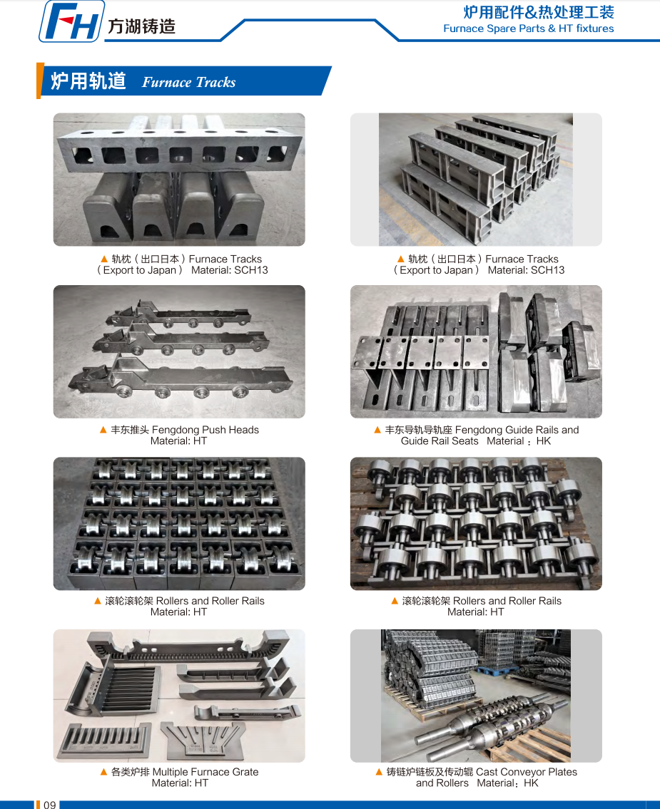
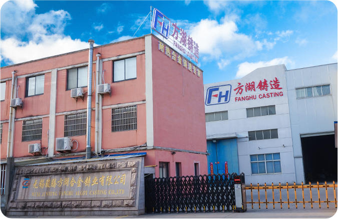
Genuine Photos of FH® Heat Treatment Fixtures
Ordering Process
1. Provide:
- Furnace type and drive mechanism (sprocket, hydraulic, screw)
- Required push force (or tray load + number of trays)
- Operating temperature (inside furnace vs cool zone)
- Tray/basket dimensions and push interface
- Chain pitch and length required
- Attachment spacing (distance between push heads)
2. FH® proposes:
- Material recommendation for push head and chain
- Push head design (shape, wear pad, guide)
- Chain specification (pitch, attachments, heat treatment)
- CAD drawing for approval
- Price and lead time
3. Production: 15–25 working days
4. Delivery includes:
- Material test certificates
- Dimensional inspection report
- Assembly drawing and installation guide
FAQ:
Q1: What is the typical service life of a push head and chain assembly?
A: With proper lubrication and alignment: push head – 2–5 years depending on temperature and push force; chain – 3–7 years for furnace-grade materials. Regular inspection for wear, elongation, or bending is recommended every 6–12 months.
Q2: What material do you recommend for a 950°C carburizing furnace push head?
A: For 950°C carburizing atmosphere, we recommend 1.4849 for the push head – excellent creep strength and carburization resistance. For the chain inside the furnace, also use 1.4849 or 310S. For chain in the cool return line, heat-treated alloy steel is sufficient.
Q3: Can you match an existing push head that is no longer available?
A: Yes – reverse engineering available. Send us your worn push head or drawings. We will measure, recommend material upgrades if beneficial, and produce a direct replacement.
Q4: How do I know when the chain needs replacement?
A: Measure chain elongation. Replace when elongation exceeds 2–3% of original length. Also inspect for worn pins, cracked side plates, or seized links. FH® offers replacement chains with the same attachment spacing.
Q5: What is your warranty?
A: 12 months against manufacturing defects (weld cracks, material flaws, machining errors). Normal wear, chain elongation, and thermal fatigue are not covered – but FH® will recommend the right materials for your specific conditions to maximize life.


 Tel: 0510-83310100
  E-mail:
  Add: Room 1105,Building 6, Jiaye Wealth Center,Wuxi, Jiangsu, P.R.China P.C.:214000.