
 English
 Español
 italiano
 Deutsch
 0086-13338774804


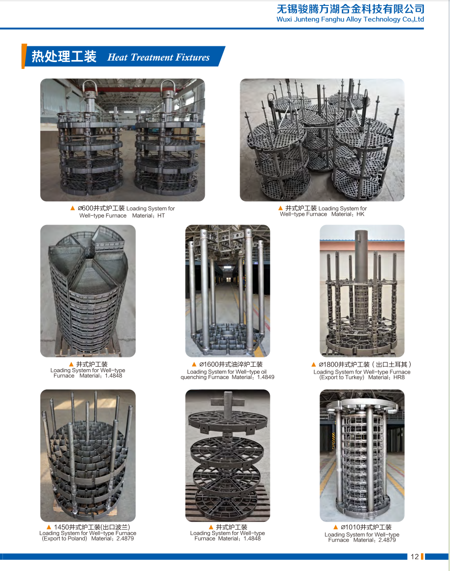
 Heat Resistant Steel Well-type Furnace Fixtures – Max 1150°C, Anti-Carburization")


FH® 1.4849 Well-type Furnace Fixture System
Key Benefits
- Genuine 1.4849 (ZG40Cr19Ni39Nb)
Higher nickel, chromium, and silicon content than 310S – exceptional creep strength and anti-carburization at temperatures up to 1050°C. - Complete System Solution
Base tray + intermediate baskets + top grid – designed as an integrated system for stable stacking and optimal gas flow. - Heavy-Load Bearing
Reinforced rib structures and support feet distribute weight evenly – supports tall stacks of parts or multiple baskets without center sagging. - Anti-Carburization Performance
High silicon content (1.5–2.5%) forms a SiO₂ barrier against carbon penetration – extends service life in rich carburizing atmospheres. - Gas Circulation Optimized
Raised feet on base tray + open grid patterns allow hot gas to flow around all surfaces – uniform heating from bottom to top. - Custom Configuration
Circular or rectangular – precisely matched to your furnace internal diameter. Segmented options for large diameters.
Technical Specifications
| Parameter | Value |
| Material | 1.4849 (ZG40Cr19Ni39Nb) – certified |
| Max. continuous temp. | 1050°C |
| Short-term peak temp. | 1100°C |
| Max. total load | 500 – 2000 kg (design dependent) |
| Fabrication | Precision laser/TIG welding or investment casting |
| Shape | Circular (standard) or rectangular |
| Standard diameters | 600 mm, 800 mm, 1000 mm, 1200 mm (custom available) |
| Expected service life | 400 – 600 carburizing cycles |
| Material test certificate (MTC) + weld/cast inspection report included with every FH® system | |
Why Choose FH® 1.4849 Well-type Furnace Fixtures?
1. 1.4849 – The Superior Choice for Well-type Furnaces
| Property | 310S | 1.4849 | Advantage |
| Creep strength at 1000°C | Baseline | +40% | Less sagging |
| Anti-carburization | Moderate | High | Longer life in rich atmosphere |
| Oxidation resistance | Good | Excellent | Less scaling |
| Thermal fatigue resistance | Good | Superior | Fewer cracks |
| Typical cycle life | 150–250 | 400–600 | 400–600 |
2. Complete System – Designed to Work Together
| Component | Function | Key Feature |
| Base tray | Foundation, gas flow | Raised feet, reinforced ribs |
| Stacking baskets | Part containment | Open grid, smooth edges |
| Top grid | Secure top layer | Weight retention, anti-tip |
3. Anti-Carburization Technology
In carburizing well-type furnaces, carbon penetrates and embrittles ordinary fixtures. FH® 1.4848 fixtures feature:
- High silicon content – forms a stable SiO₂ barrier
- Pre-oxidation treatment – creates protective Cr₂O₃ layer
- Dense surface finish – reduces carbon adhesion
4. Designed for Well-type Furnace Challenges
| Challenge | FH® Solution |
| Heavy stacks (2–3 meters tall) | Reinforced ribs + high creep strength alloy |
| Bottom layer uneven heating | Raised feet + open grid patterns |
| Difficult top access removal | Segmented options for large diameters |
| Thermal cycling stress | Rounded corners + stress-relieved welds |
Applications
- Well-type / pit carburizing furnaces
- Well-type carbonitriding furnaces
- Well-type annealing furnaces (high temperature)
- Well-type hardening furnaces
- Parts: large gears, shafts, rings, dies, tooling, heavy castings, long tubes
Material Grade Table:
| Heat-resistant Steel | |||||||||||||
| / | GB | DIN | ASTM | JIS | Chemical Composition (%) | Maximum Operation Temperature | |||||||
| C | Si | Mn | Cr | Ni | Nb/Cb | Mo | Other | ||||||
| 1 | ZG40Cr27Ni4 | 1.4823 | HD | SCH11 | 0.30 - 0.50 | ≤2.00 | ≤1.00 | 24.00 - 28.00 | 4.00 - 6.00 | - | ≤0.50 | - | 1050℃ |
| 2 | ZG40Cr22Ni10 | 1.4826 | HF | SCH12 | 0.30 - 0.50 | 1.00 - 2.50 | ≤2.00 | 19.00 - 23.00 | 8.00 - 12.00 | - | ≤0.50 | - | 950℃ |
| 3 | ZG30Cr28Ni10 | - | HE | SCH17 | 0.20 - 0.50 | ≤2.00 | ≤2.00 | 26.00 - 30.00 | 8.00 - 11.00 | - | - | - | 1050℃ |
| 4 | ZG40Cr25Ni12 | 1.4837 | HH | SCH13 | 0.30 - 0.50 | 1.00 - 2.50 | ≤2.00 | 24.00 - 27.00 | 11.00 - 14.00 | - | ≤0.50 | - | 1050℃ |
| 5 | ZG30Cr28Ni16 | - | HI | SCH18 | 0.20 - 0.50 | ≤2.00 | ≤2.00 | 26.00 - 30.00 | 14.00 - 18.00 | - | - | - | 1100℃ |
| 6 | ZG40Cr25Ni20Si2 | 1.4848 | HK | SCH21 | 0.30 - 0.50 | ≤1.75 | ≤1.50 | 23.00 - 27.00 | 19.00 - 22.00 | - | ≤0.50 | - | 1100℃ |
| 7 | ZG30Cr20Ni25 | - | HN | SCH19 | 0.20 - 0.50 | ≤2.00 | ≤2.00 | 19.00 - 23.00 | 23.00 - 27.00 | - | - | - | 1100℃ |
| 8 | ZG40Cr19Ni39 | 1.4865 | HU | SCH20 | 0.35 - 0.75 | ≤2.50 | ≤2.00 | 17.00 - 21.00 | 37.00 - 41.00 | - | - | - | 1020℃ |
| 9 | ZG40Cr15Ni35 | 1.4806 | HT | SCH15 | 0.35 - 0.70 | ≤2.00 | ≤2.00 | 15.00 - 19.00 | 33.00 - 37.00 | - | ≤0.50 | - | 1000℃ |
| 10 | ZG40Cr25Ni35Nb | 1.4852 | HPCb | SCH24Nb | 0.30 - 0.50 | ≤2.00 | ≤2.00 | 24.00 - 28.00 | 33.00 - 37.00 | 0.80 - 1.80 | ≤0.50 | - | 1100℃ |
| 11 | ZG40Cr19Ni39Nb | 1.4849 | - | - | 0.30 - 0.50 | 1.00 - 2.50 | ≤2.00 | 18.00 - 21.00 | 36.00 - 39.00 | 1.20- 1.80 | ≤0.50 | - | 1100℃ |
| 12 | ZG40Cr24Ni24Nb | 1.4855 | - | - | 0.30 - 0.50 | 1.00 - 2.50 | ≤2.00 | 23.00 - 25.00 | 23.00 - 25.00 | 0.80 - 1.80 | ≤0.50 | - | 1050℃ |
| 13 | ZG40Cr25Ni35 | 1.4857 | HP | SCH24 | 0.35 - 0.50 | 1.00 - 2.50 | ≤2.00 | 24.00 - 28.00 | 33.00 - 37.00 | - | ≤0.50 | - | 1100℃ |
| 14 | ZG1Cr20Ni32Nb | 1.4859 | - | - | 0.06 - 0.15 | 0.50 - 1.50 | ≤2.00 | 19.00 - 21.00 | 31.00 - 33.00 | 0.50 - 1.50 | ≤0.50 | - | 1050℃ |
| 15 | ZG45Cr12Ni60 | - | HW | - | 0.35 - 0.75 | ≤2.00 | ≤2.00 | 10.00 - 14.00 | 58.00 - 62.00 | - | - | - | 1100℃ |
| 16 | ZG45Cr18Ni66 | - | HX | - | 0.35 - 0.75 | ≤2.00 | ≤2.00 | 15.00 - 19.00 | 64.00 - 68.00 | - | - | - | 1100℃ |
| 17 | ZG1Cr28Co50 | 2.4778 | - | - | 0.05 - 0.25 | 0.50 - 1.00 | ≤1.50 | 27.00 - 30.00 | ≤1.00 | ≤0.50 | ≤0.50 | Co:48.0 - 52.0 | 1200℃ |
| 18 | ZG30Cr28Co50Nb | 2.4779 | - | - | 0.25 - 0.35 | 0.50 - 1.50 | 0.50 - 1.50 | 27.00 - 29.00 | - | 1.50 - 2.50 | ≤0.50 | Co:48.0 - 52.0 | 1200℃ |
| 19 | ZG40Cr28Ni48W5 | 2.4879 | - | SCH42 | 0.35 - 0.55 | 1.00 - 2.00 | ≤1.50 | 27.00 - 30.00 | 47.00 - 50.00 | - | ≤0.50 | W:4.0 - 5.5 | 1200℃ |
Genuine Photos of FH® Heat Treatment Fixtures
Ordering Process
- Provide furnace internal diameter (or L×W), depth, and access method
- Share part dimensions, max load weight per batch, and operating temperature
- Specify atmosphere (carburizing, carbonitriding, annealing, etc.)
- FH® engineers propose complete system design + 3D layout
- Confirm component quantities (one base tray + number of baskets)
- Production: 15–25 working days
- Delivery includes: MTC, inspection reports, stacking diagram, care guide
FAQ:
Q1: What does a complete FH® well-type furnace fixture system include?
A: A standard system includes three components:
- Base tray – sits on the furnace bottom with raised feet for gas circulation
- Stacking baskets – hold parts, stack on top of each other
- Top grid – secures the top layer and prevents tipping
All components are designed to work together for stable stacking and uniform heating. Custom configurations are available.
Q2: How do I determine the right fixture size for my well-type furnace?
A: We need three measurements:
- Internal diameter (or length × width for rectangular furnaces)
- Usable depth (from furnace bottom to the lowest interference point)
- Top opening diameter (for installation clearance)
FH® will then design fixtures that fit with proper clearance for gas flow and thermal expansion.
Q3: Why do I need raised feet on the base tray?
A: Raised feet create a gap (typically 50–150 mm) between the base tray and furnace bottom. This allows hot gas or atmosphere to flow under the lowest basket, ensuring uniform heating from bottom to top. Without raised feet, the bottom layer heats slower and unevenly.
Q4: Can FH® fixtures be used in both carburizing and nitriding furnaces?
A: Yes, FH® offers fixture solutions for both applications. However, we recommend dedicated fixtures for each atmosphere type when possible – switching between carburizing and nitriding can accelerate surface degradation. Please specify your atmosphere when ordering so we can recommend the optimal design.
Q5: My well-type furnace has a small top opening. How do I install large fixtures?
A: For furnaces with top opening smaller than the internal diameter, FH® offers segmented designs:
- Segmented base trays (3–4 interlocking pieces)
- Split or hinged baskets
These are installed piece-by-piece through the top opening and assembled inside the furnace. No furnace entry required.
Q6: Can you repair damaged FH® fixtures?
A: Yes, for localized damage:
- Cracked welds can be re-welded (by FH® or qualified shop)
- Minor sagging is not repairable – replacement recommended
- Severely carburized or nitrided fixtures become brittle and should be replaced
Contact FH® with photos for a repair assessment.


 Tel: 0510-83310100
  E-mail:
  Add: Room 1105,Building 6, Jiaye Wealth Center,Wuxi, Jiangsu, P.R.China P.C.:214000.