
 May 04, 2026
 Content
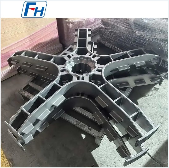
Heat Treatment Trays are core tooling components used in industrial heat treatment furnaces to hold workpieces during heating, quenching, tempering, and other thermal processes. Material selection, structural design, and manufacturing processes directly determine heat treatment quality, production efficiency, and equipment service life. Custom-built trays manufactured from premium heat-resistant alloy steels (such as 1.4848, 1.4849, 2.4879, SCH13, etc.) can operate stably long-term in high-temperature environments ranging from 900°C to 1150°C, delivering 3 to 5 times longer service life compared to ordinary carbon steel trays. These trays are indispensable key equipment in precision metalworking, aerospace, automotive manufacturing, and other sectors.
Heat treatment trays perform three core functions in industrial furnaces: load bearing, positioning, and heat transfer. Depending on furnace type and process requirements, trays can be categorized into multiple types, each structurally optimized for specific application scenarios.
| Application Field | Typical Processes | Operating Temperature Range | Core Requirements for Trays |
|---|---|---|---|
| Aerospace | Solution treatment, aging treatment | 980°C–1150°C | High-temperature creep resistance, dimensional stability |
| Automotive Manufacturing | Carburizing quenching, nitriding | 850°C–1050°C | Thermal fatigue resistance, anti-carburizing deformation |
| Precision Metalworking | Annealing, normalizing, quenching and tempering | 700°C–950°C | Hardness uniformity, surface quality maintenance |
| Power & Energy | High-temperature annealing, stress relieving | 900°C–1100°C | Oxidation resistance, long service life |
| General Machinery | Batch quenching, tempering | 800°C–1000°C | Cost-effectiveness, universal compatibility |
Material selection for heat treatment trays is the primary factor determining their performance and service life. Different alloy compositions impart distinct high-temperature performance and mechanical characteristics.
| Material Grade | Main Alloy Elements | Maximum Service Temperature | Core Advantages | Typical Applications |
|---|---|---|---|---|
| 1.4848 | Cr 25-28%, Ni 18-21% | 1050°C | Excellent oxidation and carburization resistance | Roller hearth furnaces, annealing furnace trays |
| 1.4849 | Cr 24-26%, Ni 19-22%, Nb added | 1100°C | Outstanding high-temperature creep resistance | Aerospace high-temperature processing |
| 2.4879 | Cr 20-23%, Ni 35-39%, Co 15-18% | 1150°C | Highest strength retention at extreme temperatures | Multi-purpose furnaces, high-load furnaces |
| SCH13 | Cr 24-28%, Ni 11-14% | 1000°C | High cost-performance ratio, excellent castability | Automated continuous furnace lines |
Core Principles for Material Selection: Trays operating in carburizing atmospheres should prioritize high-chromium-nickel alloys (such as 1.4848, 1.4849), because chromium forms a dense Cr₂O₃ protective film on the surface that effectively prevents carbon atom penetration into the matrix. In pure oxidation atmospheres, nickel content can be appropriately reduced to control costs, but chromium content must remain above 20% to maintain oxidation resistance.
Structural design of heat treatment trays requires balancing load-bearing capacity, thermal uniformity, and thermal stress relief. Improper structure is the main cause of premature tray failure (deformation, cracking, creep collapse).
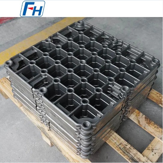
Manufacturing of heat treatment trays involves precision casting, welding, or forging processes. Quality control at each stage directly impacts the reliability and service life of the final product.
For trays with complex shapes featuring numerous ribs and open structures, precision casting (investment casting or sand casting) is the preferred process. Cast trays enable near-net-shape forming with material utilization rates up to 70% or higher, uniform internal structure, and no weld heat-affected zones. Cast trays using vacuum melting and directional solidification technology demonstrate 25% to 35% higher high-temperature rupture strength than welded structures, particularly suitable for high-load continuous operating environments.
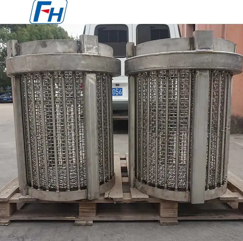
Welded trays are suitable for large or extra-large specifications (single piece weight exceeding 500kg). Welding must use heat-resistant filler materials matching the base metal, with strict control of heat input. Post-weld solution treatment at 1050°C to 1100°C is mandatory to eliminate welding residual stresses and restore corrosion resistance. Weld quality must be verified through radiographic testing (RT) or ultrasonic testing (UT) to ensure absence of lack of fusion, porosity, and other defects.
Even with the highest quality materials and processes, heat treatment trays have limited service life under harsh operating conditions. Scientific maintenance strategies can extend average service life by 30% to 50%.
| Failure Mode | Cause | Typical Life Impact | Preventive Measures |
|---|---|---|---|
| High-temperature creep deformation | Long-term overheating or overloading | Service life reduced by over 50% | Strictly control furnace loading, select higher-grade materials |
| Thermal fatigue cracking | Rapid heating and cooling cycles | Service life reduced by approximately 40% | Optimize heating and cooling rates, avoid direct water cooling |
| Carburization embrittlement | Chromium depletion in carburizing atmosphere | Service life reduced by over 60% | Select high-chromium materials, periodic decarburization treatment |
| Oxide scale spalling | Excessive oxide film thickness and detachment | Accelerated substrate loss | Control furnace oxygen content, periodic oxide scale removal |
While standardized trays offer versatility and economy, customized designs can significantly improve heat treatment quality and production efficiency in specific process scenarios.
Customized heat treatment trays are recommended when the following conditions occur:
Professional tray custom design requires users to provide the following technical parameters: furnace type and effective working zone dimensions, maximum operating temperature and temperature uniformity requirements, single-piece and total weight of furnace-loaded workpieces, process atmosphere type (oxidation/carburizing/nitriding/vacuum), loading/unloading method (manual/forklift/robotic arm), expected service life target. Based on these parameters, engineers can use finite element analysis (FEA) to simulate thermal and mechanical stress distribution, optimize structure, and predict service life.
Focus on Designing and Manufacturing Alloy Steel Parts since 2006
 Tel: 0510-83310100
  E-mail: [email protected]
  Office Add: Room 1105,Building 6, Jiaye Wealth Center,Wuxi, Jiangsu, P.R.China P.C.:214000.
  Privacy

 English
 Español
 italiano
 Deutsch
 0086-13338774804