
 Sep 09, 2026
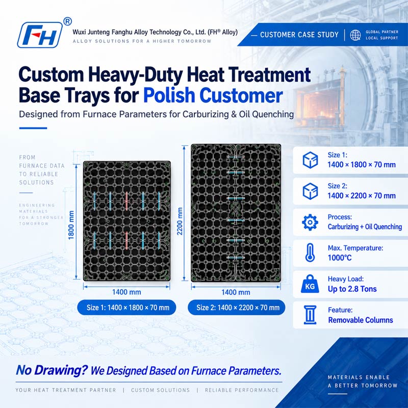
 Custom Heavy-Duty Heat Treatment Base Trays for a Polish Customer
Customer Case Study | Engineering Design, Manufacturing & Delivery
Customer Location: Poland
Product: Custom Heat Treatment Base Trays
Application: Carburizing & Oil Quenching
Designed Sizes:
Maximum Process Temperature: 1000°C
Oil Quenching Temperature: Approx. 100°C
Furnace Load: Up to 2.8 tons depending on furnace size
Service Scope: Engineering Design + Manufacturing + Delivery
Manufacturer: Wuxi Junteng Fanghu Alloy Technology Co., Ltd. (FH® Alloy)
Project Overview
FH® Alloy completed a customized heat treatment base tray project for a customer in Poland.
Unlike a conventional build-to-print order, the customer did not have finished tray drawings. Instead, they provided the main furnace operating conditions, loading dimensions, heat treatment process and required furnace load.
Based on these technical inputs, FH® Alloy was responsible for developing the tray structures, preparing the engineering drawings, manufacturing the finished products and arranging shipment.
Two main tray sizes were developed for this project:
The trays were designed for a demanding carburizing process at temperatures up to 1000°C, followed by immersion in quenching oil at approximately 100°C.
Customer Operating Conditions
The customer supplied FH® Alloy with the following application data.
| Item | Customer Requirement |
| Customer Location | Poland |
| Product | Heat Treatment Base Tray |
| Process | Carburizing + Oil Quenching |
| Maximum Temperature | 1000°C |
| Oil Quenching Temperature | Approx. 100°C |
| Tray Size 1 | 1400 × 1600 × 70 mm |
| Tray Size 2 | 1400 × 2200 × 70 mm |
| Furnace Load for 2200 × 1400 | Approx. 2.8 tons |
| Furnace Load for 1800 × 1400 | Approx. 2 tons |
| Additional Furnace Size | 1600 × 1400 mm |
| Furnace Load for 1600 × 1400 | Approx. 2 tons |
| Column Requirement | Removable columns depending on load |
| Customer Drawing | Not available |
| FH® Alloy Scope | Design, Manufacturing & Delivery |
Customer Challenge: No Finished Drawing
One of the most important characteristics of this project was that the Polish customer did not provide an existing production drawing.
The customer mainly supplied:
FH® Alloy therefore needed to convert these operating parameters into a practical and manufacturable tray structure.
This required engineering evaluation rather than simple dimensional copying.
Engineering Challenge: Large Size + Heavy Load + Thermal Cycling
The trays were relatively large, particularly the 1400 × 2200 × 70 mm version.
Large furnace trays operating under heavy loads at elevated temperatures face several engineering risks.
High-Temperature Deformation
At carburizing temperatures approaching 1000°C, the mechanical strength of heat-resistant alloys decreases compared with room-temperature conditions.
If the support structure is not properly designed, the tray may experience:
For a tray as large as 1400 × 2200 mm, this becomes especially important.
Heavy Furnace Loading
According to the customer's operating information, the furnace loading conditions could reach:
The customer also indicated that the tray loading requirement could be close to the furnace's overall loaded condition in certain applications.
This required the tray design to provide effective load distribution across a large surface area.
Rapid Temperature Change During Oil Quenching
The heat treatment cycle includes:
Carburizing at up to 1000°C → Oil Quenching at approximately 100°C
This represents a substantial temperature difference.
Repeated exposure to these cycles can generate:
The tray structure therefore needed to consider both static loading and repeated thermal cycling.
FH® Alloy Engineering Design
FH® Alloy developed two customized tray structures based on the customer's furnace sizes and load conditions.
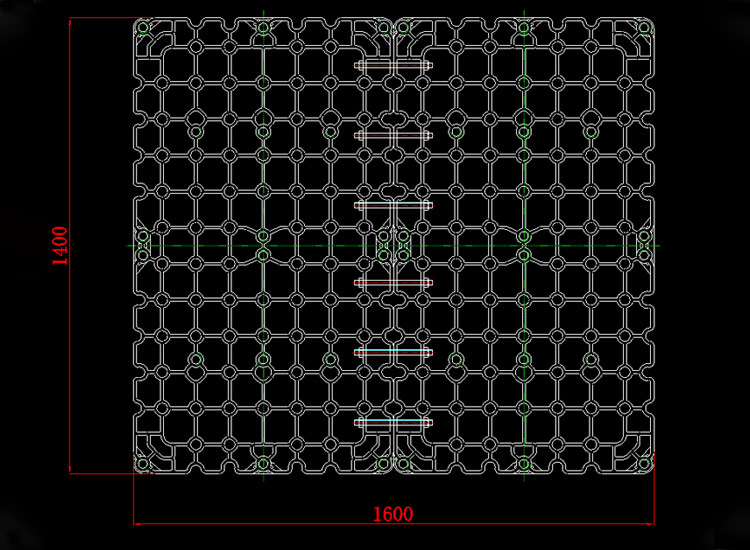
1400 × 1600 × 70 mm Base Tray
The first tray was designed with overall dimensions of:
1400 × 1600 × 70 mm
The structure uses a repeated grid-type load-bearing layout to distribute load across the tray surface.
The design also incorporates strategically located connection and support positions so that the tray can work together with removable vertical columns when required.
Key design objectives included:
1400 × 2200 × 70 mm Base Tray
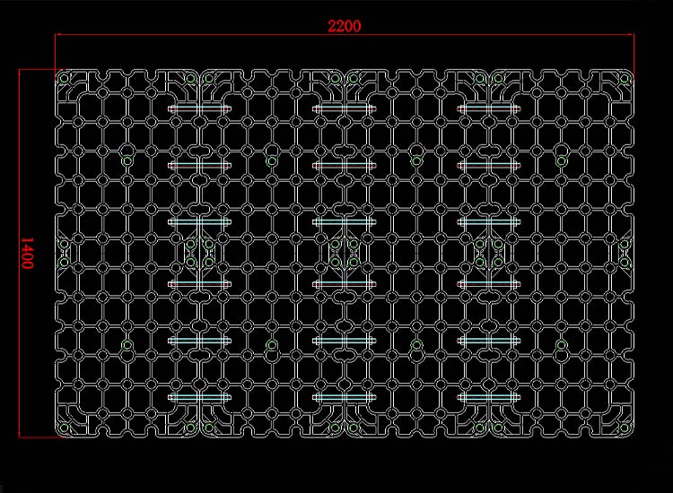
The second design was a larger tray:
1400 × 2200 × 70 mm
Because of the increased length, structural control became even more important.
The final drawing incorporated multiple structural sections and reinforcing connections to maintain stability over the larger working area.
The 2200 mm version was developed for furnace conditions with loads of up to approximately 2.8 tons.
The engineering focus included:
Grid-Type Structural Design
Both tray concepts use an open grid structure.
This type of structure provides several advantages in heat treatment applications.
Improved Load Distribution
The interconnected support ribs help transfer loads across multiple structural paths rather than concentrating stress in a small number of members.
Reduced Self-Weight
An open structure provides high structural efficiency without making the entire tray unnecessarily solid and heavy.
Better Process Circulation
The open geometry allows furnace atmosphere and quenching media to move through the tray more effectively.
Thermal Expansion Management
A properly designed grid structure can help accommodate thermal expansion during repeated heating and cooling cycles.
Removable Column Design
The customer specifically requested:
FH® Alloy therefore incorporated column mounting positions into the tray design.
This allows the customer to configure the fixture according to different loading requirements.
When additional vertical support is required, columns can be installed at designated positions.
When the production setup does not require them, the columns can be removed.
This provides greater flexibility compared with a completely fixed fixture structure.
Design Based on Actual Furnace Load
A major consideration in this project was that different furnace sizes had different loading capacities.
For example:
2200 × 1400 Furnace
Approximate furnace load:
2.8 tons
1600 × 1400 Furnace
Approximate furnace load:
2 tons
Rather than using exactly the same structure for every furnace size, FH® Alloy evaluated the relationship between:
Tray Size + Furnace Load + Support Position + High-Temperature Conditions
and developed the designs accordingly.
From Operating Parameters to Final Engineering Drawings
This project followed a complete engineering process.
Customer Furnace Information
↓
Heat Treatment Process Review
↓
Loading Requirement Analysis
↓
Structural Concept Development
↓
Removable Column Positioning
↓
Engineering Drawing
↓
Manufacturing
↓
Inspection
↓
Shipment
The customer provided the furnace conditions rather than finished drawings, and FH® Alloy converted those requirements into two production-ready base tray designs.
Project Specifications
| Item | Specification |
| Product | Heat Treatment Base Tray |
| Customer | Polish Customer |
| Application | Carburizing & Oil Quenching |
| Design 1 | 1400 × 1600 × 70 mm |
| Design 2 | 1400 × 2200 × 70 mm |
| Maximum Working Temperature | 1000°C |
| Quenching Medium | Oil |
| Approx. Oil Temperature | 100°C |
| Maximum Referenced Furnace Load | Approx. 2.8 tons |
| Structure | Open Grid Load-Bearing Design |
| Column System | Removable Depending on Load |
| Customer Drawing | Not Provided |
| Engineering Drawing | Designed by FH® Alloy |
| Project | Scope Design + Manufacturing + Delivery |
Why This Project Is Different from Build-to-Print Manufacturing
Many heat treatment fixture projects begin with a complete customer drawing.
This project did not.
The Polish customer provided process and furnace information, while FH® Alloy took responsibility for converting those requirements into a workable engineering solution.
The project therefore demonstrates FH® Alloy's capability in:
This capability is particularly valuable for customers who know their furnace conditions but do not yet have a finalized fixture drawing.
Custom Heat Treatment Tray Design by FH® Alloy
Wuxi Junteng Fanghu Alloy Technology Co., Ltd. (FH® Alloy) designs and manufactures customized heat treatment tooling for demanding industrial furnace applications.
Our product range includes:
Customers can provide either complete drawings or basic engineering information such as:
Furnace Size + Temperature + Load + Heat Treatment Process + Cooling Method + Workpiece Information
FH® Alloy can then support the project from engineering design through manufacturing.
Need a Custom Heavy-Duty Furnace Tray?
If your existing furnace tray deforms under high-temperature or heavy-load conditions, or if you have furnace parameters but no finished fixture drawing, FH® Alloy can help develop a customized solution.
For engineering evaluation, please provide:
FH® Alloy supports custom furnace tooling from engineering design to finished production and delivery.
About FH® Alloy
Wuxi Junteng Fanghu Alloy Technology Co., Ltd. (FH® Alloy) specializes in custom high-temperature alloy components and heat treatment furnace tooling for global industrial customers.
Our capabilities include engineering design, heat-resistant alloy casting, machining, assembly and customized furnace fixture manufacturing.
Custom Design | Heavy Load Solutions | High-Temperature Tooling | Manufacturing
Request a Custom Furnace Tray Design
Send Your Furnace Parameters
View Heat Treatment Fixtures
 CategoryRecent Post

Focus on Designing and Manufacturing Alloy Steel Parts since 2006
 Tel: 0510-83310100
  E-mail: info@alloy-casting.com
  Office Add: Room 1105,Building 6, Jiaye Wealth Center,Wuxi, Jiangsu, P.R.China P.C.:214000.
  Privacy

 English
 Español
 italiano
 Deutsch
 0086-13338774804
