
 May 11, 2026
 Content
Heat treatment fixtures serve as the essential interface between workpieces and thermal processing equipment. Their design rationality, material selection, and manufacturing quality directly govern the uniformity, repeatability, and final product quality of the entire heat treatment cycle. In industrial production, approximately 30%–40% of heat treatment defects—such as distortion, oxidation, and uneven carburization—are directly attributable to improper fixture design or usage. Therefore, selecting the right heat treatment fixture is not a secondary operational decision but a strategic factor that determines the success or failure of the thermal process.
From a practical engineering perspective, heat treatment fixtures must simultaneously satisfy three core performance criteria: high-temperature structural stability (maintaining shape and load-bearing capacity at target temperatures), thermal conductivity efficiency (ensuring uniform heating of workpieces), and chemical compatibility (avoiding adverse reactions with furnace atmospheres or workpiece surfaces). The absence of any one of these metrics will result in elevated batch scrap rates or significantly increased energy consumption.
The primary considerations for heat treatment fixture materials are persistent strength at elevated temperatures, oxidation resistance, and carburization resistance. Different alloys are suited to distinct process temperatures and atmospheric conditions; incorrect material selection remains one of the leading causes of premature fixture failure.
| Material Grade | Max. Service Temperature | Primary Alloying Elements | Typical Applications |
|---|---|---|---|
| 1.4848 (GX25CrNiSi18-9) | ≤ 950°C (1,742°F) | Cr 18%, Ni 9%, Si 1.5% | Carburizing, carbonitriding fixtures |
| 1.4852 (GX40NiCrSi35-17) | ≤ 1,150°C (2,102°F) | Ni 35%, Cr 17%, Si 2% | High-temperature quenching, annealing fixtures |
| 2.4879 (NiCr23Co12Mo) | ≤ 1,250°C (2,282°F) | Ni balance, Cr 23%, Co 12% | Deep pit furnace high-temp carburizing fixtures |
| HR4 / ZG40Cr15Ni35 | ≤ 1,050°C (1,922°F) | Cr 15%, Ni 35%, C 0.4% | Aerospace, automotive batch heat treatment |
| Cr25Ni20 (310S) | ≤ 1,100°C (2,012°F) | Cr 25%, Ni 20% | Vacuum furnaces, protective atmosphere furnaces |
Heat treatment fixtures face multiple degradation risks during prolonged high-temperature cyclic service. The most prevalent failure modes include:
To mitigate these failure modes, engineering practice typically employs the following measures: selecting nickel-based high-alloy materials to enhance creep resistance; applying anti-oxidation coatings to fixture surfaces; optimizing heating-cooling rates to reduce thermal shock; and establishing regular inspection and replacement protocols to catch degradation before catastrophic failure.
Different furnace types impose fundamentally different requirements on fixture geometry, dimensional accuracy, and loading methodology. A mismatch between fixture and furnace not only reduces production efficiency but can also create safety hazards.
| Furnace Category | Typical Fixture Forms | Core Design Requirements | Loading Characteristics |
|---|---|---|---|
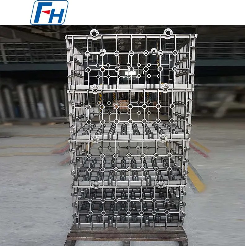
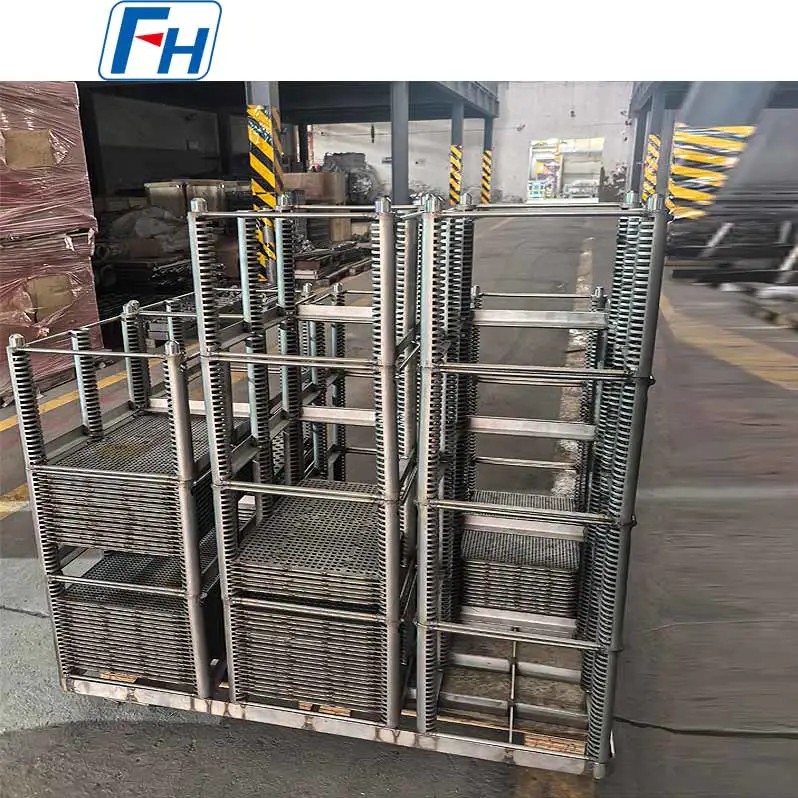
| Box Furnace | Trays, baskets, multi-tier racks | Planar stability, stackability | Medium batch, multi-layer loading |
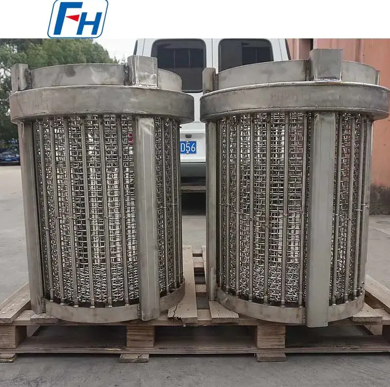
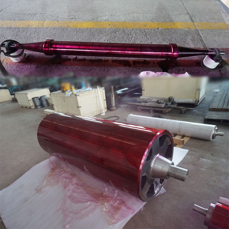
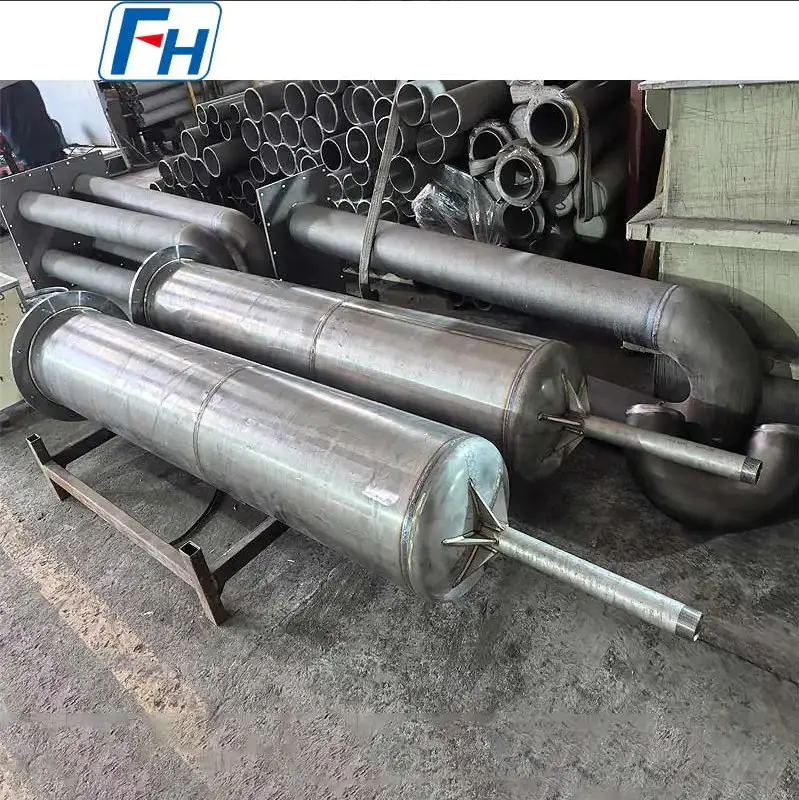
| Pit (Well-type) Furnace | Suspension rigs, vertical racks, circular bases | Vertical suspension strength, concentricity | Long-axis workpiece dedicated |
| Vacuum Furnace | Vacuum baskets, graphite/metal hybrid fixtures | Low outgassing, high-temp strength retention | Precision small batch, high-value parts |
| Pusher/Roller Hearth Continuous Furnace | Pallets, trays, dedicated jigs | Wear resistance, push compatibility | Large-volume continuous production |
| Bogie Hearth Furnace | Large structural racks, modular bases | Overall rigidity, bogie interface match | Oversized, heavy workpieces |
Fixture structural design demands a careful balance between loading density and heat flow uniformity. In carburizing processes, for example, insufficient workpiece spacing restricts atmosphere circulation and produces uneven case depths; excessive spacing reduces furnace loading capacity and increases unit energy consumption. Engineering experience indicates that the minimum gap between adjacent workpieces in carburizing fixtures should be maintained at 15–25 mm to ensure adequate atmosphere circulation.
Fixture dead weight is another critical factor. In pit furnace applications, the combined weight of fixture and workpieces often reaches hundreds of kilograms to several tons, requiring suspension and support structures designed with ample safety margins—typically a safety factor no lower than 3.0. Furthermore, the thermal mass of the fixture itself directly affects heating time and energy consumption; lightweight design offers significant value in energy savings. Every 10% reduction in fixture weight can shorten heating time by an average of 5%–8%.
Heat treatment fixture manufacturing primarily follows three process routes: casting, welding/assembly, and precision machining. Each route is suited to different complexity levels and precision requirements.
Quality control for heat treatment fixtures spans the entire manufacturing process, with key inspection nodes including:
The service life of heat treatment fixtures varies significantly depending on material, process, and operating conditions. Under conventional carburizing conditions (930°C, 8–12 hour cycle), typical service lives for different material fixtures are as follows:
| Material | Typical Service Life (Cycles) | Primary Failure Mode |
|---|---|---|
| 1.4848 | 300 – 500 | Carburization embrittlement, distortion |
| 1.4852 | 600 – 900 | Thermal fatigue cracking |
| 2.4879 | 1,000 – 1,500 | Gradual creep deformation |
| HR4 / ZG40Cr15Ni35 | 400 – 700 | Oxidation wastage, distortion |
Extending fixture service life and reducing per-heat-treatment costs can be approached from multiple dimensions:
Faced with numerous material, structural, and supplier options, a systematic selection framework enables optimal decision-making. The following priority sequence is recommended for evaluation:
By applying this systematic framework, manufacturers can achieve optimal economic efficiency in fixture investment while securing the quality foundation necessary for continuous improvement in heat treatment processes.
Focus on Designing and Manufacturing Alloy Steel Parts since 2006
 Tel: 0510-83310100
  E-mail: [email protected]
  Office Add: Room 1105,Building 6, Jiaye Wealth Center,Wuxi, Jiangsu, P.R.China P.C.:214000.
  Privacy

 English
 Español
 italiano
 Deutsch
 0086-13338774804