
 Mar 27, 2026
 Content
Radiant tubes are sealed, gas-tight heating elements used in industrial furnaces to transfer heat to workpieces indirectly — without exposing the heated material to combustion gases. In simple terms, a radiant tube burns fuel inside a closed tube; the tube wall heats up and radiates thermal energy into the furnace chamber, keeping the atmosphere inside the furnace completely separate from the flame.
This design is essential for controlled-atmosphere heat treatment processes such as annealing, hardening, carburizing, and sintering, where even trace amounts of combustion byproducts (water vapor, CO₂, oxygen) would oxidize or otherwise damage the workpiece surface.
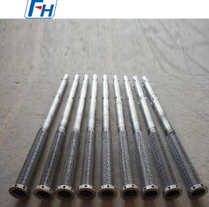
Radiant tubes are manufactured from high-temperature alloys (e.g., HK-40, HP, RA330) or advanced ceramics (SiC, Si₃N₄), and are available in several geometric configurations suited to different furnace layouts and thermal requirements.
The shape of a radiant tube directly affects how evenly heat is distributed across the furnace load. The four most widely used configurations are:
| Type | Shape | Heat Uniformity | Typical Application |
|---|---|---|---|
| Straight (I-type) | Linear single pass | Moderate | Roller hearth, pusher furnaces |
| U-type | Single return bend | Good | Batch furnaces, side-mounted heating |
| W-type | Double return bend | Very good | Continuous belt furnaces |
| P-type (Radial) | Concentric tube-in-tube | Excellent | High-uniformity annealing lines |
The P-type (radial) design is especially valued in applications demanding temperature uniformity within ±5 °C, since its concentric geometry distributes the flame evenly around the circumference of the outer tube.
Radiant tubes serve three core functions in industrial heating systems:
By enclosing combustion entirely within a sealed tube, radiant tubes allow the furnace interior to be filled with a protective or reactive atmosphere — nitrogen, hydrogen, endothermic gas, or vacuum — without contamination from flame gases. This is critical for bright annealing of stainless steel and copper, where oxidation must be reduced to near-zero levels.
The tube wall, heated to between 900 °C and 1 150 °C in most metallic alloy tubes (up to 1 350 °C for SiC ceramic tubes), emits infrared radiation that warms the furnace load uniformly. This mechanism avoids the hot spots and flame impingement damage that direct-fired burners can cause on sensitive parts.
Modern radiant tube assemblies are paired with recuperative or regenerative burners that reclaim heat from exhaust gases and preheat combustion air, routinely achieving thermal efficiencies of 60–80%. A recuperative radiant tube system can reduce natural gas consumption by 25–40% compared to a conventional open-flame furnace of similar output.
The choice of tube material determines maximum operating temperature, service life, and total cost. The two main categories are metallic alloys and ceramics:
Ceramic tubes cost 2–4× more than comparable metallic alloy tubes upfront, but their longer service life and ability to operate at higher temperatures can make them economically favorable in continuous high-temperature processes.
Radiant tubes are found wherever precise, atmosphere-controlled heat treatment is required. Key industries include:
Selecting the wrong tube specification leads to premature failure, uneven heating, or unnecessary cost. Evaluate the following parameters:
| Parameter | Typical Range | Impact on Performance |
|---|---|---|
| Max. tube surface temperature | 900–1 350 °C | Determines alloy or ceramic choice |
| Heat flux density | 15–60 kW/m² | Affects tube wall stress and life |
| Furnace atmosphere | H₂, N₂, endogas, vacuum | Determines corrosion/carburization risk |
| Cycling frequency | Continuous to 10+ cycles/day | Thermal fatigue resistance priority |
| Required temperature uniformity | ±2 to ±15 °C | Drives choice of tube geometry |
Service life varies considerably by material, operating temperature, and process conditions. In a well-maintained continuous annealing furnace running at ~1 000 °C, metallic alloy tubes (HK-40 or HP) typically last 3–6 years. SiC ceramic tubes in similar service can last 8–12 years, though they are more susceptible to mechanical breakage during installation and maintenance. Tubes subjected to aggressive carburizing atmospheres or rapid thermal cycling may fail in as little as 12–18 months if the alloy grade is not properly matched to the environment.
The most common failure modes are:
Minor surface cracks or pinholes in metallic tubes can sometimes be repaired by qualified welders using matching filler material, but this is generally a short-term measure. Once a tube shows significant wall thinning (more than 20–25% of original thickness) or through-wall cracking, full replacement is the recommended and safer course of action. Ceramic tubes cannot be welded and must be replaced when cracked.
Both types recover heat from exhaust gases, but they do so differently:
Regenerative burner systems have a higher capital cost but are preferred for furnaces operating continuously above 1 100 °C.
Yes, and this is increasingly important as the steel and metals industry moves toward decarbonization. Radiant tubes can burn 100% hydrogen with appropriate burner adjustments, since hydrogen has a much higher flame speed and lower ignition energy than natural gas. The key challenge is that hydrogen combustion produces only water vapor, which at high temperatures can cause oxidation of some alloy grades. Higher-chromium alloys (≥25% Cr) and SiC ceramic tubes are preferred for hydrogen-fired radiant tube applications due to their stronger resistance to steam oxidation.
A leak allows combustion gases to enter the furnace atmosphere, which can be detected by:
Operators who achieve the longest tube service lives consistently follow these practices:
Radiant tube heating is not always the right choice. Understanding the trade-offs helps engineers make the correct decision:
| Criterion | Radiant Tube Heating | Direct-Fired Heating |
|---|---|---|
| Atmosphere control | Excellent — fully isolated | None — combustion gases present |
| Surface finish of parts | Bright, oxide-free possible | Scale formation likely |
| Capital cost | Higher | Lower |
| Thermal efficiency | 60–80% (with recuperation) | 50–70% |
| Max. furnace temperature | Up to ~1 300 °C (SiC tubes) | Up to 1 600 °C+ |
| Best for | Annealing, sintering, hardening | Reheating, forging, glass melting |
The decision rule is straightforward: if the process demands a specific furnace atmosphere or a clean workpiece surface, radiant tube heating is the technically correct solution, regardless of slightly higher capital cost. For bulk reheating where surface oxidation is tolerable and removed in a subsequent step, direct firing is more economical.
Focus on Designing and Manufacturing Alloy Steel Parts since 2006
 Tel: 0510-83310100
  E-mail: [email protected]
  Office Add: Room 1105,Building 6, Jiaye Wealth Center,Wuxi, Jiangsu, P.R.China P.C.:214000.
  Privacy

 English
 Español
 italiano
 Deutsch
 0086-13338774804