The selection and design of heat treatment fixtures is a systematic engineering task that requires comprehensive consideration of process requirements, material characteristics, production efficiency, and cost-effectiveness. Below are the key principles and steps:
1. Core Design Principles
01. High-Temperature Resistance & Thermal Fatigue Resistance
- Materials must withstand the maximum operating temperature (e.g., 1000°C for quenching, 600°C for tempering) and endure repeated heating/cooling stresses.
- Priority should be given to heat-resistant steels (e.g., Cr-Ni series: 310S/RA330 for temperatures above 1000°C; 2520-type for temperatures below 950°C).
02. Balance Between Strength and Rigidity
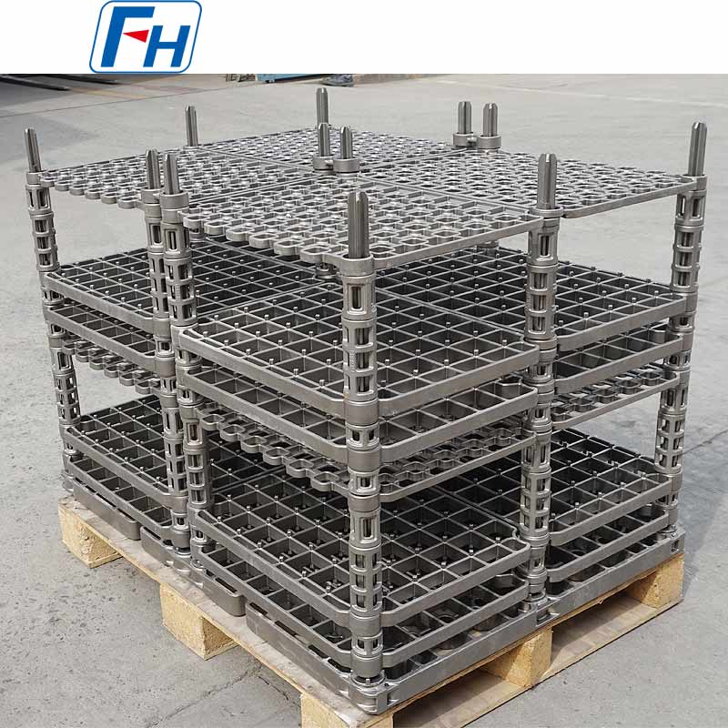
- Calculate workpiece weight and stacking methods to avoid deformation at high temperatures.
- Adopt truss structures or reinforcing ribs in design to reduce weight while ensuring load-bearing capacity.
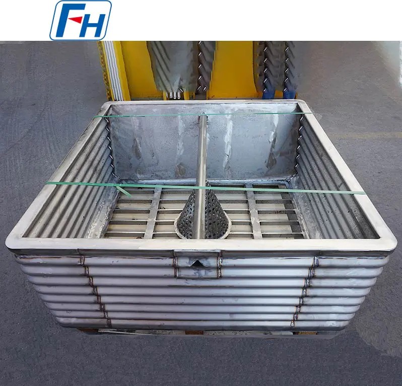
03. Optimization of Heat Transfer & Atmosphere Circulation
- Avoid blocking radiation heating channels; use open structures (e.g., grids, open-area ratio ≥30%).
- Ensure uniform furnace atmosphere flow to prevent soft spots or uneven case depth on workpieces.
04. Resistance to Environmental Corrosion
- Select materials based on furnace atmosphere:
- Carburizing/Carbonitriding: Choose high-nickel alloys (e.g., RA333) to resist carburization embrittlement.
- Salt Bath/Vacuum Furnaces: Avoid contact between dissimilar metals to prevent low-melting eutectic reactions.
- Oxidizing Atmospheres: Apply surface coatings (e.g., aluminosilicon diffusion coatings) for protection.
05. Workpiece Compatibility & Damage Prevention
- Minimize contact area at support points (e.g., knife-edge supports) to reduce heat transfer obstruction and sticking.
- For precision parts (e.g., gears), use contoured fixtures to prevent quenching distortion.
2. Material Selection Guide
| Temperature Range |
Recommended Materials |
Typical Applications |
| ≤600°C |
Mild Steel (Q235) |
Tempering, aging fixtures |
| 600–900°C |
2535/2540 (25Cr2Mo1V) |
Quenching trays, racks |
| 900–1100°C |
310S/RA330 (25Cr20Ni) |
Carburizing furnaces, high-temperature solution fixtures |
| >1100°C |
RA333/Nickel-based alloys (e.g., Inconel 601) |
Ultra-high-temperature sintering, brazing |
- Cost-Efficiency Tip: Use high-performance materials only in critical high-temperature zones; combine with lower-grade materials for non-critical areas via welding.
3. Design Steps & Validation
01. Define Process Parameters
- Temperature profile, atmosphere type, loading capacity, cooling method (oil/gas quenching).
02. 3D Modeling & Simulation
- Use Thermo-Calc or ANSYS to analyze thermal stress distribution and optimize weak areas.
- Simulate furnace airflow to validate the layout of openings.
03. Key Design Details
- Weld Locations: Avoid high-stress areas; use groove welding with nickel-based electrodes (e.g., ENiCrFe-3).
- Dimensional Allowances: Account for thermal expansion coefficients (e.g., ~16×10⁻⁶/°C for 310S) with appropriate gaps.
- Lifting Structures: Add lifting lugs and reinforcing ribs for safe handling.
04. Prototype Testing
- Conduct no-load thermal cycling tests to measure deformation; trial production runs to check workpiece uniformity.
4. Common Pitfalls & Solutions
| Problem |
Likely Cause |
Improvement Measures |
| Premature fixture cracking |
Unrelieved welding residual stress |
Perform post-weld stress relief annealing (900°C soak) |
| Uneven workpiece hardness |
Blocked airflow |
Add side ventilation holes; optimize layer spacing |
| Severe sticking |
Similar fixture/workpiece materials |
Apply ceramic coatings (e.g., Al₂O₃) to contact surfaces |
| High energy consumption |
Excessive fixture dead weight |
Switch to honeycomb core panels to reduce weight by ~30% |
5. Full Lifecycle Management
01. Coding & Traceability System: Establish a record for each fixture, documenting material, usage cycles, and maintenance history.
02. Regular Inspection Standards:
- Mandatory correction if deformation exceeds 50% of workpiece tolerance.
- Grit blasting required if oxide scale thickness exceeds 1mm.
03. Scrap Criteria:
- Cracks appear in critical load-bearing structures.
- Weight increase >20% after multiple repairs (impacts energy efficiency).
6. Innovation Trends
- Lightweight Composite Materials: Carbon fiber-reinforced silicon carbide (C/SiC) for vacuum furnaces, reducing weight by >60%.
- 3D-Printed Conformal Cooling Channels: Designed for complex geometries to achieve uniform quenching.
- Smart Fixtures: Embedded thermocouples for real-time temperature monitoring and dynamic process adjustments.
Practical Recommendations
- “Simulate Before Manufacturing”: Conduct thermo-mechanical coupled simulations before production to avoid ~80% of early failures.
- “Zonal Design”: Use higher-grade materials or add thermal insulation in areas with steep temperature gradients (e.g., near furnace doors).
- “Maintenance as Investment”: Regular removal of carbon buildup and oxide scale can extend fixture life by over 30%.

 Dec 19, 2025
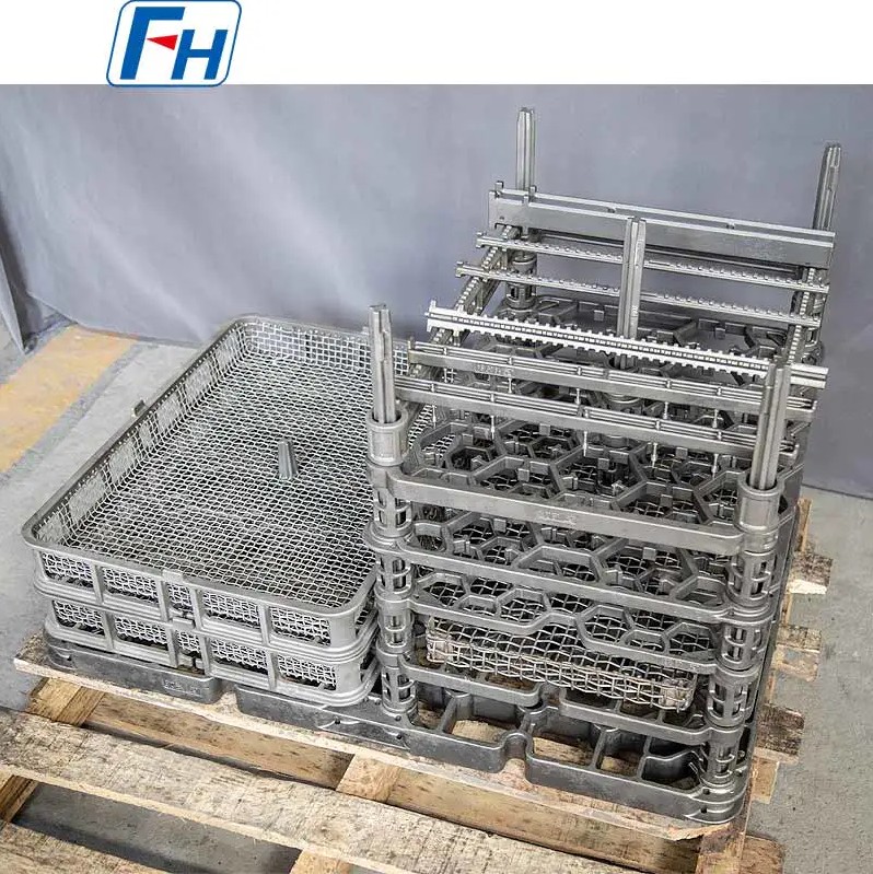
 Tel: 0510-83310100
  E-mail: [email protected]
  Office Add: Room 1105,Building 6, Jiaye Wealth Center,Wuxi, Jiangsu, P.R.China P.C.:214000.
  Privacy

 English
 Español
 italiano
 Deutsch
 0086-13338774804